
Connector for electronically connecting a cable and a printed circuit board

a technology of electronic connection and printed circuit board, which is applied in the direction of telephony connection, electrical apparatus, connections, etc., to achieve the effect of reducing the cost of incoming materials and simple structur

Inactive Publication Date: 2008-05-27
ALTEK CORP
View PDF5 Cites 16 Cited by
  • Summary
  • Abstract
  • Description
  • Claims
  • Application Information

AI Technical Summary

Benefits of technology

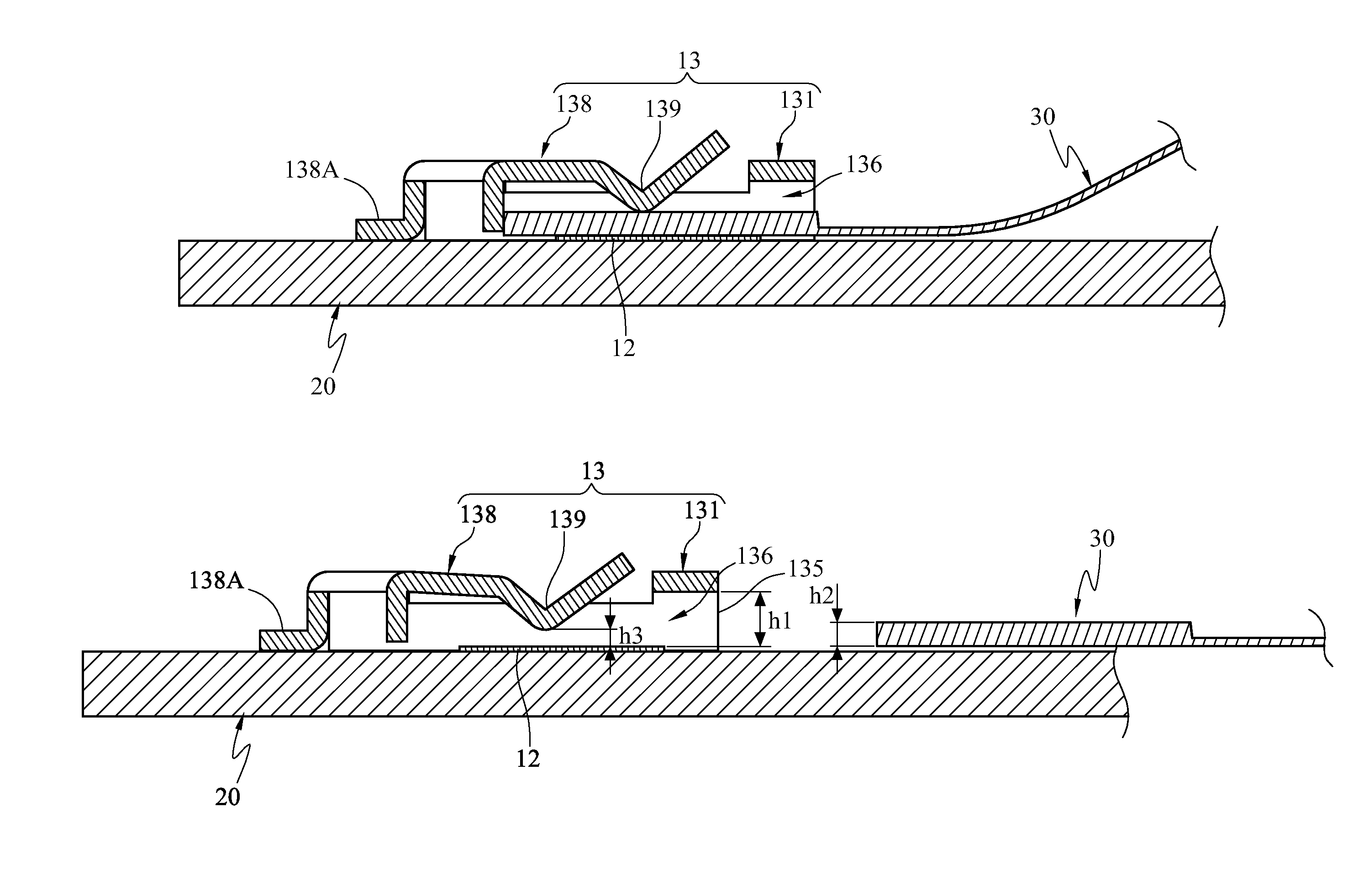
"The present invention provides an electrical connector structure that has a simple structure, reduces material cost, and achieves close contact between different electronic devices. The structure includes a plurality of electrical terminals and a sleeve lid with a positioning part that extends from the lid body. The accommodation space formed by the lid body and the PCB allows for direct contact between the FFC and the PCB, reducing the space required and the volume of the connector. The blade spring assists in achieving close contact without the risk of loose contact. The invention simplifies the process of forming and assembling the structure and reduces the number of devices needed, while reducing material cost."

Problems solved by technology

In addition, the electrical connector structure assisted with the pressing positioning scheme of the blade spring may indeed achieve the effect of close contact of the FFC and the PCB, and the disadvantage of a loose contact does not occur.

Method used


Image

  • Connector for electronically connecting a cable and a printed circuit board
  • Connector for electronically connecting a cable and a printed circuit board
  • Connector for electronically connecting a cable and a printed circuit board

Examples


Embodiment Construction

[0021]The present invention provides an electrical connector structure, which is applicable in, but not limited to, FPC boards, FFCs, and the like. For example, the structures for establishing electrical connections for individual electronic devices and a combination thereof may also use the technology disclosed in the present invention. In the following detailed illustration of the present invention, the FPC board and the FFC are used as the application embodiment of the present invention.

[0022]As shown in FIGS. 3A and 3B, the electrical connector structure 10 comprises a plurality of electrical terminals 12 and a sleeve lid 13. The plurality of electrical terminals 12 of the electrical connector structure 10 is nakedly disposed on a PCB 20. The sleeve lid 13 has a lid body 131 and a positioning part 132 extending from an end of the lid body 131. The lid body 131 further has a top wall 133 and a side wall 134, and the sleeve lid 13 has an opening 135, therefore, with an open space ...


PUM


Abstract

An electrical connector structure is provided. The electrical connector structure is applicable in an electronic device having a printed circuit board (PCB), and is electrically connected with the PCB via a flexible flat cable (FFC). The electrical connector structure includes a plurality of electrical terminals disposed on the PCB, and a sleeve lid disposed at the position corresponding to the electrical terminals. The sleeve lid is formed with an opening. The FFC extends into the opening to contact the electrical terminals. A blade spring disposed on the surface of the sleeve lid is used to press the FFC, making its contact with the electrical terminals compact.

Description

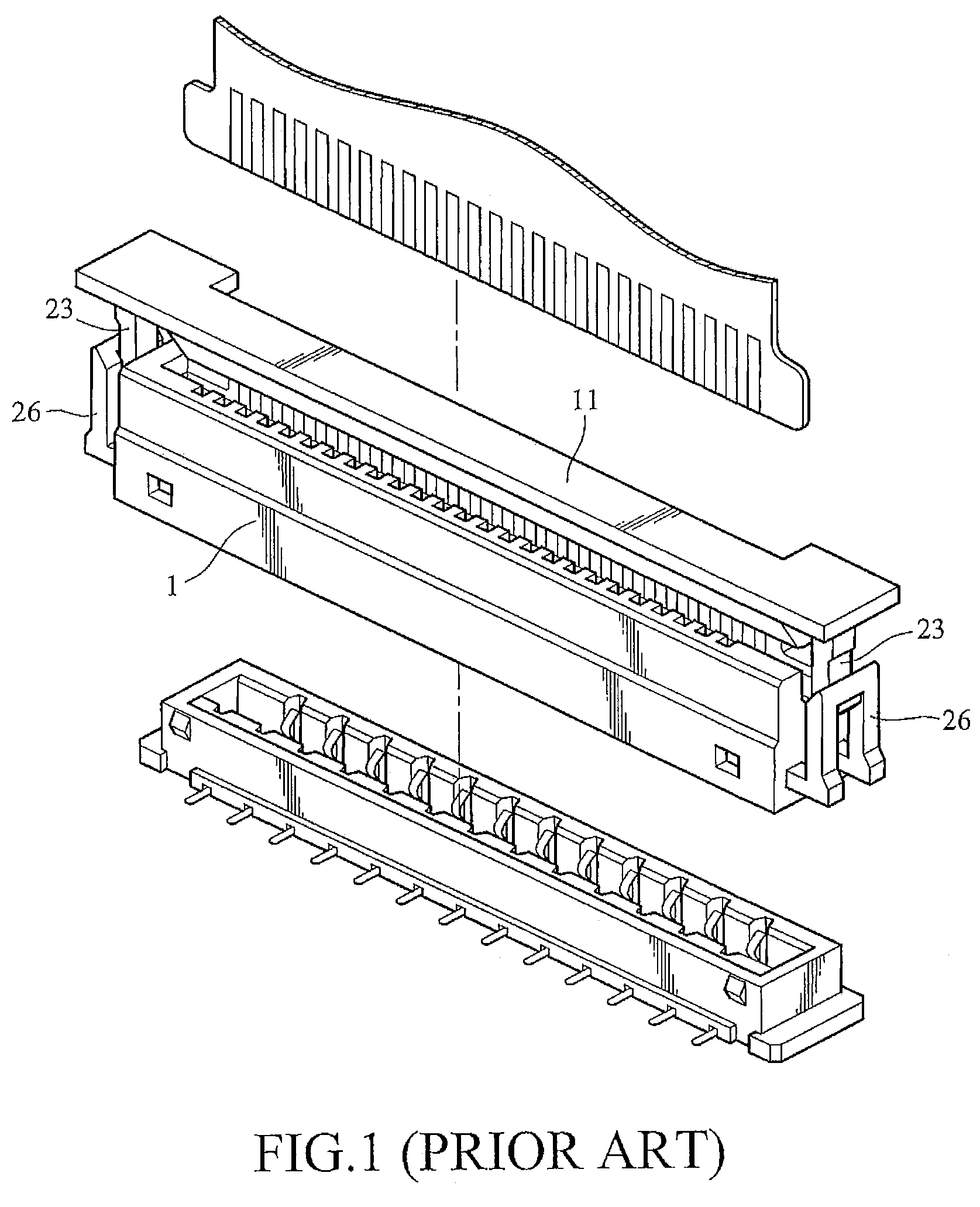
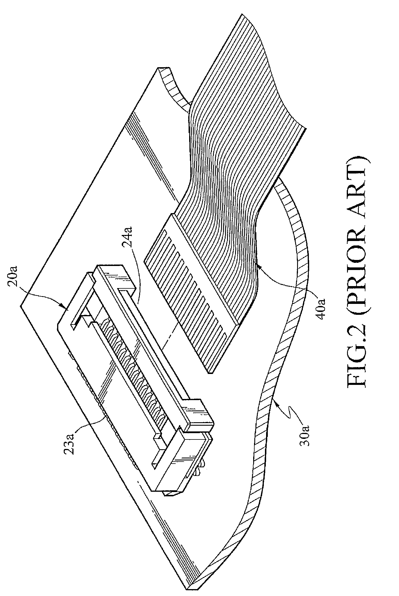
CROSS-REFERENCE TO RELATED APPLICATIONS[0001]This non-provisional application claims priority under 35 U.S.C. §119(a) on Patent Application No(s). 095111064 filed in Taiwan, R.O.C. on Mar. 29, 2006 the entire contents of which are hereby incorporated by reference.BACKGROUND OF THE INVENTION[0002]1. Field of Invention[0003]The present invention relates to an electrical connector structure, and more particularly, to an electrical connector structure applicable in a flexible printed circuit board or a flexible flat cable.[0004]2. Related Art[0005]A connector is an important component for connecting circuits or signals between electronic apparatuses. The application field of the connector is quite wide. Industries such as computer, communication, and data transmission, even medical treatment, industrial electronic measuring instruments and automobiles all need to use connectors. However, with the trend of development of smaller and thinner electronic apparatuses, a flexible printed circ...

Claims


Application Information

Patent Timeline
Patent Type & Authority Patents(United States)
IPC IPC(8): H01R12/24
CPCH01R12/62H01R12/721H01R2201/16
Inventor LIN, TZU-CHIH
Owner ALTEK CORP
Learn More