
Disk drive actuator latch apparatus and method

a technology of actuator latch and disk drive, which is applied in the field of disk drive, can solve the problems of difficult control of servo current, damage to the read/write head and the recording surface, etc., and achieve the effect of lowering the magnetic attraction

Inactive Publication Date: 2008-05-20
SAMSUNG ELECTRONICS CO LTD
View PDF15 Cites 4 Cited by
  • Summary
  • Abstract
  • Description
  • Claims
  • Application Information

AI Technical Summary

Benefits of technology

The present invention provides an actuator latch apparatus for a disk drive that can change latch forces depending on the locking or unlocking of the actuator. This allows for better control and efficiency in the operation of the disk drive. The actuator latch apparatus includes a swing arm, a VCM coil, a magnet, and a yoke. The actuator latch apparatus can lock the actuator by magnetically attracting the swing arm to the yoke using a magnet and a solenoid coil. The actuator latch apparatus can also release the actuator by applying a current to the solenoid coil. The invention also includes a magnetic interfering apparatus that reduces the required torque for unlocking the actuator latch apparatus. The actuator latch apparatus and the method of locking the actuator can improve the performance and reliability of the disk drive.

Problems solved by technology

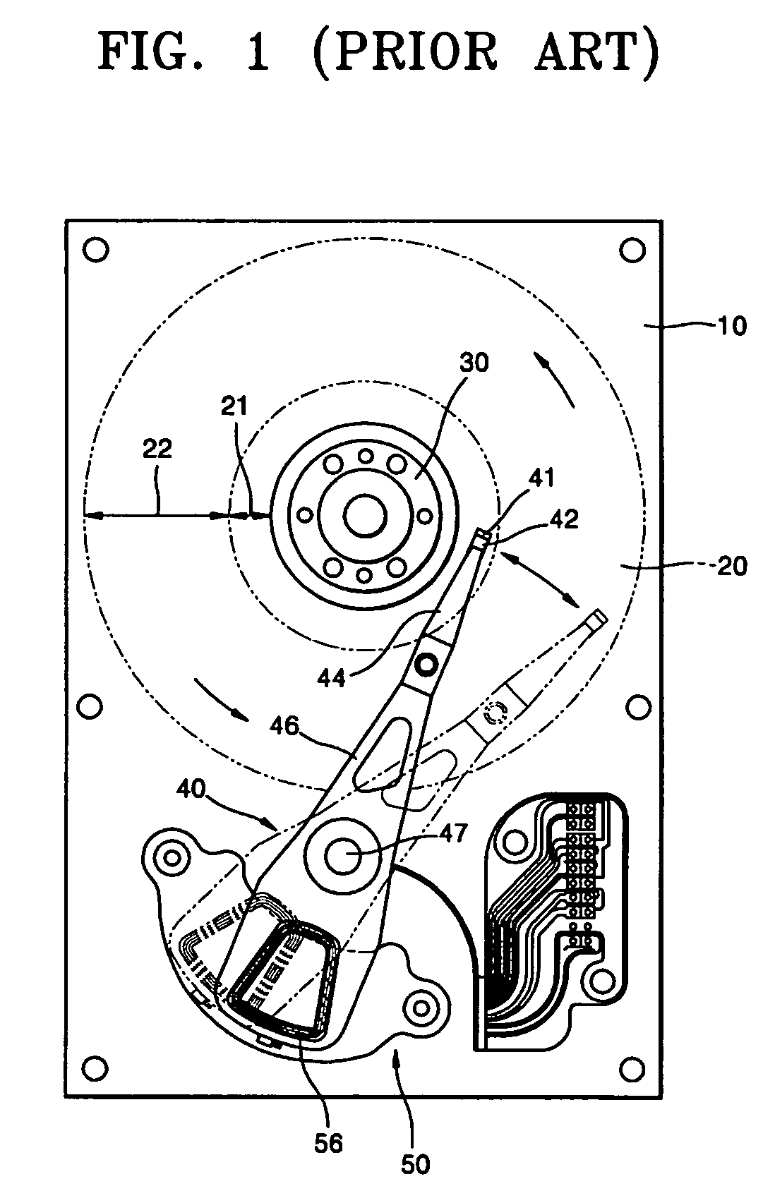
In this case, the read / write head can make forceful contact with the recording surface of the disk, such that the read / write head and the recording surface may be damaged.
However, it is very difficult to control servo current, for applying the brake to the swing arm 46.

Method used


Image

  • Disk drive actuator latch apparatus and method
  • Disk drive actuator latch apparatus and method
  • Disk drive actuator latch apparatus and method

Examples


Embodiment Construction

[0042]Reference will now be made in detail to the embodiments of the present invention, examples of which are illustrated in the accompanying drawings, wherein like reference numerals refer to the like elements throughout. The embodiments are described below to explain the present invention by referring to the figures.

[0043]FIG. 4 is an exploded perspective view of an actuator provided with an actuator latch apparatus, according to an embodiment of the present invention, and FIG. 5 is an enlarged perspective view of the actuator latch apparatus shown in FIG. 4.

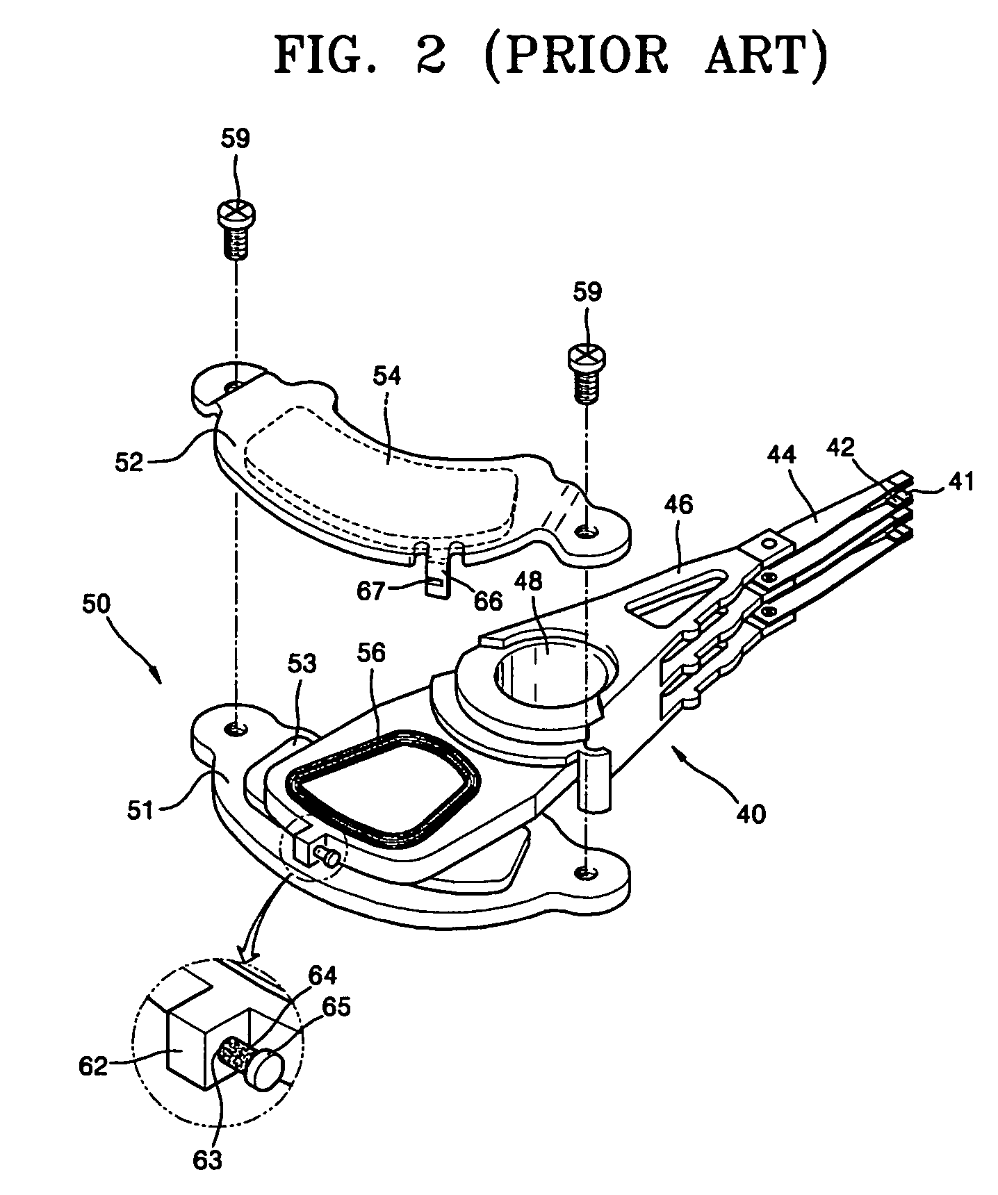
[0044]Referring to FIGS. 4 and 5, an HDD can be provided with an actuator 140, carrying a read / write head 141 to a desired position of a disk. The actuator 140 is provided with a swing arm 146, rotatably installed on a base member of the HDD. The swing arm 146 is formed with a pivot hole 148, in a central portion thereof, for the rotatable installation. The swing arm 146 can usually be made by a plastic injection molding proce...


PUM

PropertyMeasurementUnit
magnetic forceaaaaaaaaaa
magneticaaaaaaaaaa
outer circumferenceaaaaaaaaaa

Abstract

An actuator latch apparatus for a disk drive. The latch apparatus includes a metal piece disposed at one end of the swing arm, an attracting part protruded from an edge of the yoke, for attracting the metal piece by a magnetic force of the magnet, a hole formed at a position corresponding to the metal piece of the attracting part, for leaking magnetic flux flowing through the attracting part, a core disposed to move through the hole, and a core transfer device for transferring the core in one direction such that a leading end portion of the core is inserted into the hole when the disk drive operates, and for transferring the core in an opposite direction such that the core is released from the hole when the disk drive is stopped. Accordingly, a locking state of the actuator can be maintained more stably and released more easily.

Description

CROSS-REFERENCE TO RELATED APPLICATIONS[0001]This application claims the priority of Korean Patent Application No. 10-2004-0039628, filed on Jun. 1, 2004, in the Korean Intellectual Property Office, the disclosure of which is incorporated herein in its entirety by reference.BACKGROUND OF THE INVENTION[0002]1. Field of the Invention[0003]Embodiments of the present invention relate to a disk drive, and more particularly, to an actuator latch apparatus and a disk drive, with the same, locking an actuator in a predetermined position when a disk is not rotating, such that the actuator is prevented from arbitrarily rotating, e.g., due to an impact.[0004]2. Description of the Related Art[0005]A hard disk drive (HDD) is one of the data storage devices of a computer. The HDD reproduces data from a rotating disk and records data on the disk with a read / write head. In such an HDD, the read / write head reaches a desired position while moving above a recording surface of the rotating disk by way ...

Claims


Application Information

Patent Timeline
Patent Type & Authority Patents(United States)
IPC IPC(8): G11B5/54G11B21/22
CPCG11B5/54G11B21/22
Inventor KIM, YOUN-TAI
Owner SAMSUNG ELECTRONICS CO LTD
Learn More