
Autostereoscopic display

a display and autostereoscopic technology, applied in the field of autostereoscopic display, can solve the problems of affecting the display effect, affecting the effect of the image, and the two images producing only a limited “look around” capability, so as to achieve the effect of improving efficiency

Inactive Publication Date: 2008-05-20
KONINKLIJKE PHILIPS ELECTRONICS NV
View PDF15 Cites 67 Cited by
  • Summary
  • Abstract
  • Description
  • Claims
  • Application Information

AI Technical Summary

Benefits of technology

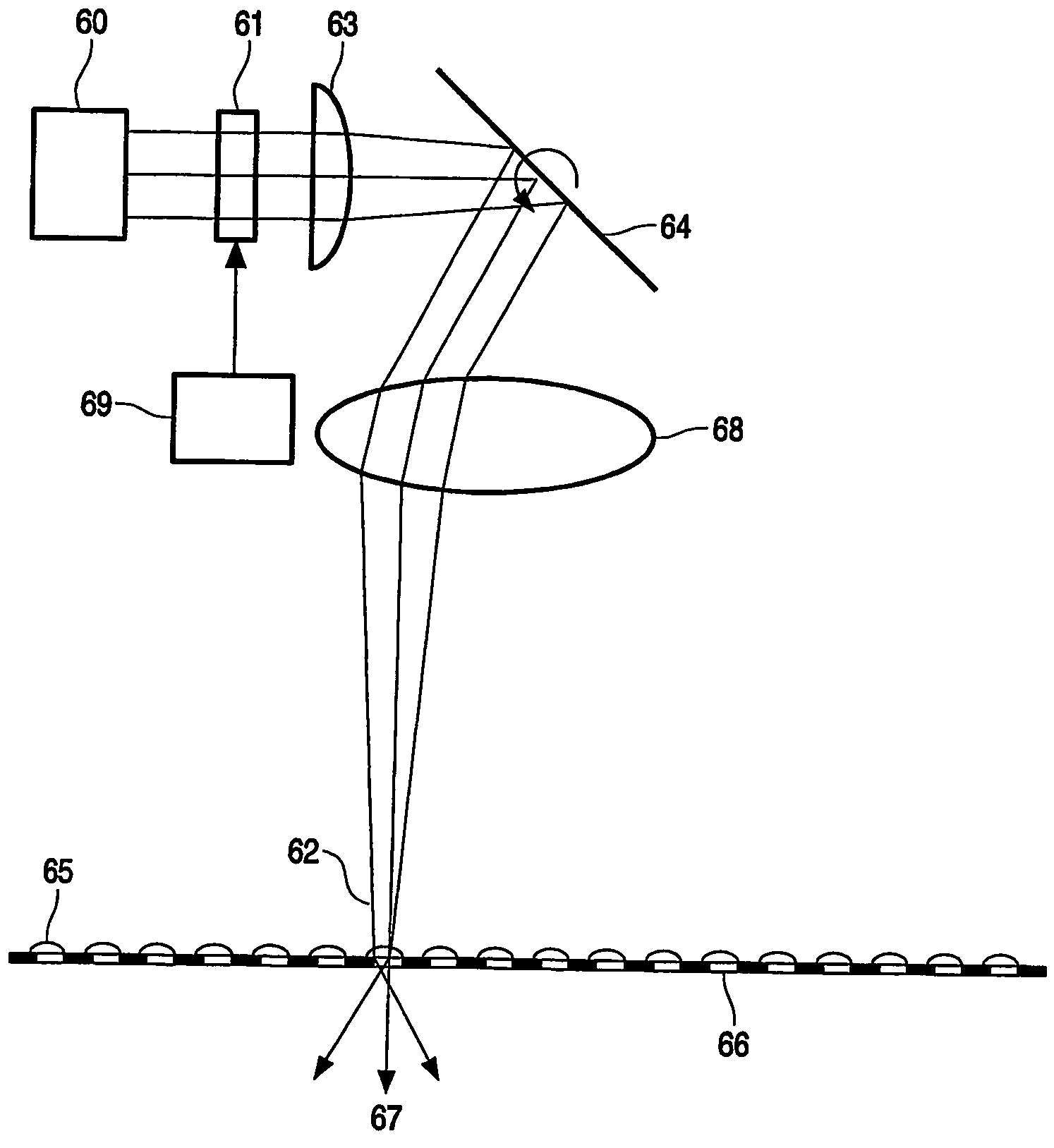
The invention is a device that provides autostereoscopic views with improved efficiency. It uses a display screen with openings and a scanning means to sequentially scan over the openings. The device emits collimated light from the pixels of the display array, which is focused in a direction perpendicular to the cylindrical lens. The display screen has a high efficiency since all the light emitted by the display array is used. The device can be used in both 2D and 3D modes and provides a large number of viewing zones without the need for goggles or poor efficiency. The use of cylindrical lenses on or near the display screen is preferred to increase the viewing angle. The synchronization of the display and the scanning means is important for good performance. A slit shadow mask can be used to improve performance, but it reduces brightness. The display screen can also have index light sensors and the signal from them fed back to the scanning means.

Problems solved by technology

A disadvantage of most multiplanar displays is that the voxels produce light, but do not block it.
This leads to transparent objects, giving quite literally a ghostly and unpleasant appearance to the displayed images.
A disadvantage with such as system is that the two images produce only a limited “look around” capability.
Furthermore, glasses have to be worn to produce any effect.
This is unpleasant for those observers who are not familiar with wearing glasses and a potential problem for those already wearing glasses, since the extra pair of glasses do not always fit.
Although these displays are autostereoscopic in the sense that no special glasses are required to view the 3D image, they often work only for one viewer at a fixed position in space.
Outside the viewing zone, the observer sees multiple images or a stereo inversion, leading to a very unpleasant view.
Solution which offer multi-view images do so at the cost of resolution.
Although it is possible to obtain a multiview autostereoscopic display in the manner described in U.S. Pat. No. 5,969,850, a drawback of the above described principle is a lack of efficiency.
Although the efficiency can be improved by making several slots of the dynamic barrier transparent at the same time, the principle problem of a very poor efficiency remains and in order to be able to use several slots the amount of different viewing directions has to be compromised

Method used


Image

  • Autostereoscopic display
  • Autostereoscopic display
  • Autostereoscopic display

Examples


Embodiment Construction

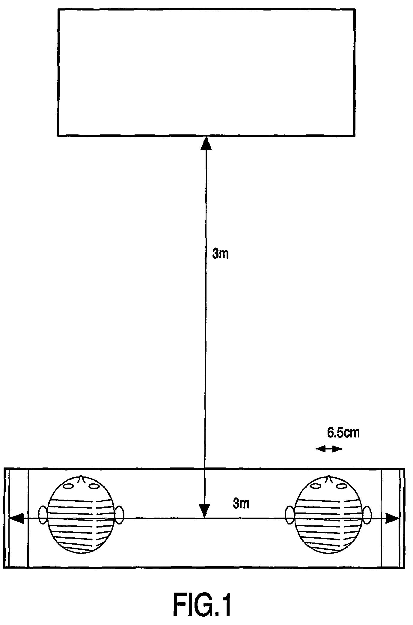
[0029]FIG. 1 illustrates a display device. For a three-dimensional television one needs a large number of viewing directions in which light is emitted independently. In a domestic application, the viewing distance is approximately 3 m and people sits on a couch that is approximately 3 m wide, see illustration 1. So, a viewing angle of at least 60-degrees is needed. Our eyes are positioned at 6:5 cm from each other. To arrive at different pictures for each eye, the display needs to emit light in at least 3 m / 6:5 cm=300 / 6:5=50 directions. To arrive at a three-dimensional picture without discontinuous transitions if one moves one's head, a three-dimensional television should emit light in much more than 50, say at least 100, directions.

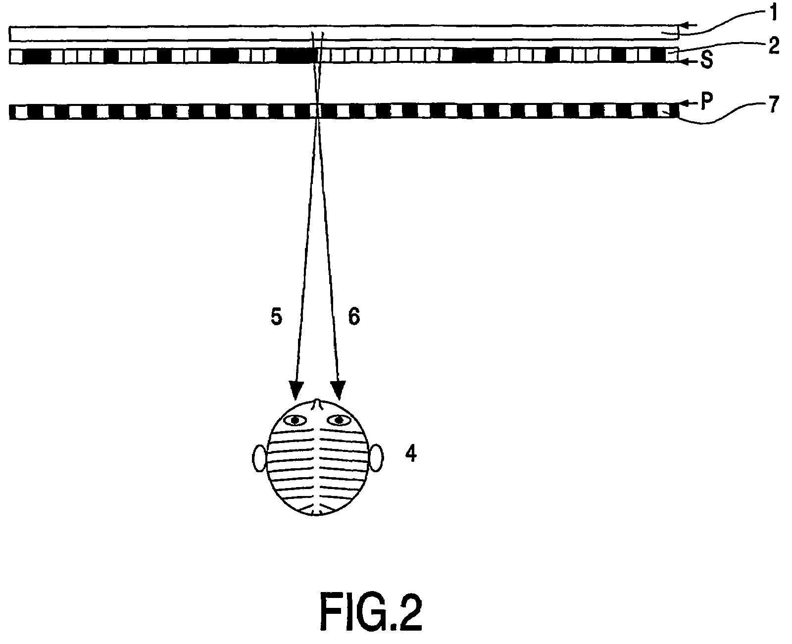
[0030]FIG. 2 illustrates the basic principle of a parallax barrier splitting two stereo images. The vertical lines of two stereo images are alternatingly displayed on, e.g., a spatial light modulator 2 (e.g. a LCD) with a back light 1. The grating struct...


PUM


Abstract

In an autostereoscopic display, a cylindrical lens focuses collimated light emitted from pixels of a display array, and a scanning device sequentially provides the light to openings in a display screen. The image information is provided in the display area at a rate corresponding to the frequency of the scanning of the openings in the display screen to provide the autostereoscopic image.

Description

[0001]The invention relates to an autostereoscopic display device comprising a display array comprising a number of addressable pixels, and a means for addressing the pixels in the display array.BACKGROUND OF THE INVENTION[0002]An autostereoscopic display device of the type described in the opening paragraph is known from U.S. Pat. No. 5,969,850.[0003]Basically, a three dimensional impression can be created by using stereo pairs (two different images directed at the two eyes of the viewer), holographic techniques, or multiple planes in the displays. With the multiplanar techniques, a volumetric image is constructed, in which the 2D pixels are replaced by so-called voxels in a 3d volume. A disadvantage of most multiplanar displays is that the voxels produce light, but do not block it. This leads to transparent objects, giving quite literally a ghostly and unpleasant appearance to the displayed images.[0004]Stereoscopic displays do not suffer from this problem. There are several ways ...

Claims


Application Information

Patent Timeline
Patent Type & Authority Patents(United States)
IPC IPC(8): G02B27/22H04N13/305G02B30/27
CPCG02B27/2214H04N13/0404H04N13/0406H04N13/0409H04N13/0454H04N13/305H04N13/31H04N13/359H04N13/307G02B30/27H04N13/00
Inventor IJZERMAN, WILLEM LUBERTUSKRIJN, MARCELLINUS PETRUS CAROLUS MICHAEL
Owner KONINKLIJKE PHILIPS ELECTRONICS NV
Learn More