
Cable guide of a cable winch

a cable guide and winch technology, applied in the field of cable guide winches, can solve the problems of tooling costs and segmental growth, and achieve the effect of easy adaptation

Active Publication Date: 2008-05-20
KONECRANES GLOBAL
View PDF12 Cites 9 Cited by
  • Summary
  • Abstract
  • Description
  • Claims
  • Application Information

AI Technical Summary

Benefits of technology

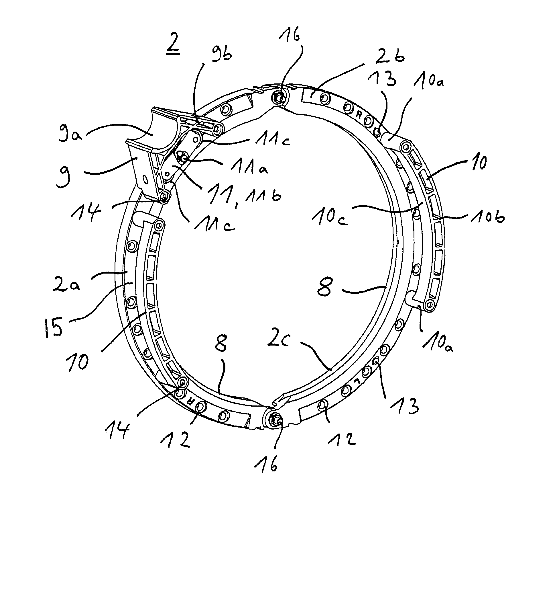
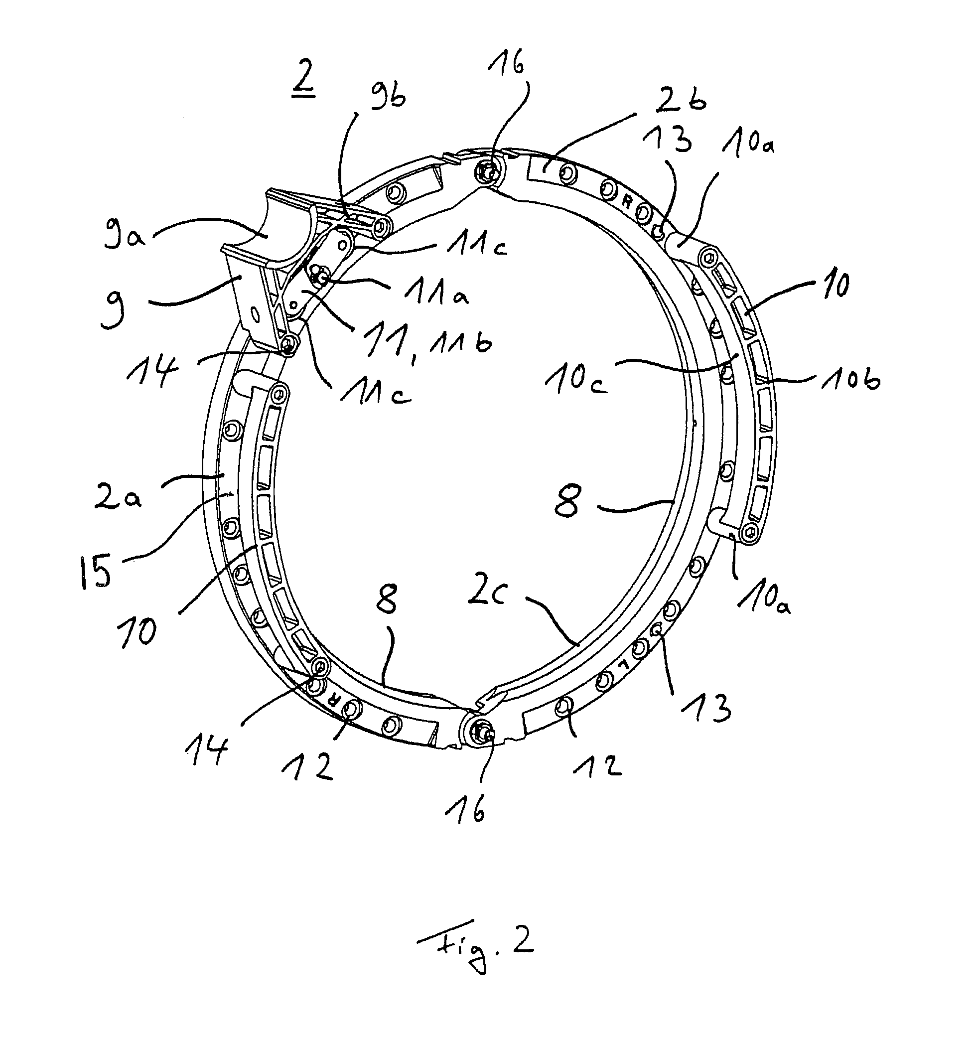
[0005]According to the invention, a cable guide of a cable winch, such as a cable hoisting winch, includes a cable drum, having at least one cable groove. The cable guide has at least two base segments expanding into a ring, which are guided in the cable groove by at least one engaging element and supported against the cable winch by a torque support. Elements for guiding and holding down a cable are arranged on the base segments. The base segments are configured such that at least one torque support and at least one add-on element for guiding and holding down a cable are arranged in a desired number variably on the base segments. Each individual component is of rather simple configuration in itself and is adapted to perform a function. A modular construction of the cable guide is achieved. The cable guide is easily adapted to accommodate the particular local circumstances, such as installation position of the cable winch and location of the cable pay-out point.
[0006]Because the base segments are identical except for the engaging elements, the diversity of parts can be reduced. Because only one basic die is required, production by plastics injection molding is simplified. The engaging elements which differ from each other can be produced by using gates or interchangeable inserts in the basic die during manufacturing. This benefit is maximized for large cable drum diameters and correspondingly large base segments.
[0013]Optionally, at least the base segments are made of plastic, in particular, a polyamide with an admixture of MoS2, which results in the base segment having good wearing and sliding properties.

Problems solved by technology

As the diameter of the cable drum becomes larger, the segments also grow in size, as do the tooling costs.

Method used


Image

  • Cable guide of a cable winch
  • Cable guide of a cable winch
  • Cable guide of a cable winch

Examples


Embodiment Construction

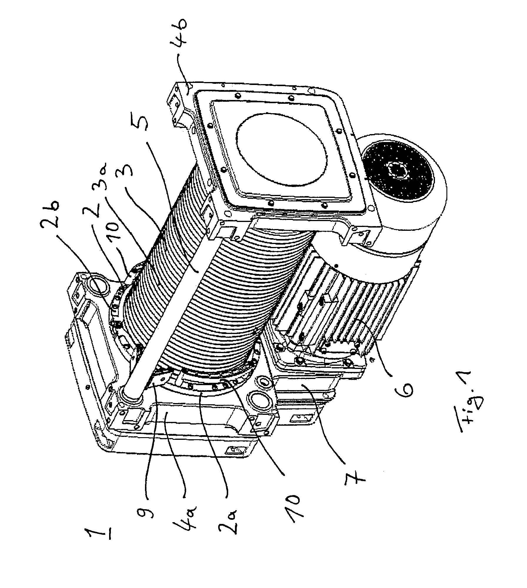
[0018]Referring now to the drawings and the embodiments illustrated therein, FIG. 1 shows a perspective view of a cable block 1 with a cable guide 2 according to the invention. The cable block 1 comprises a cable drum 3 with a cable groove 3a for a hauling cable, not shown, as well as a first support plate 4a and a second support plate 4b, between which the cable drum 3 is mounted and is able to turn. The approximately square support plates 4a and 4b are joined together and spaced from each other by two tubular lengthwise girders 5. (The second girder 5 is concealed by the cable drum 3 in FIG. 1). The ends of lengthwise girders 5 are fastened in the corner regions of the support plates 4a, 4b. The two lengthwise girders 5 are secured at opposite corners of the support plates 4a, 4b. Cable drum 3 is driven by an electric motor 6, which is joined to the cable drum 3 by a gearbox 7. Gear box 7 thrusts against the side of the first support plate 4a, away from cable drum 3.

[0019]Cable gu...


PUM


Abstract

A cable guide of a cable winch, such as a cable hoisting winch, includes a cable drum having at least one cable groove and a cable guide having at least two base segments expanding into a ring. The two base segments are guided in the cable groove by at least one engaging element and are supported against the cable winch by at least one torque support. Elements for guiding and holding down a cable are arranged on the base segments. To create a simplified and optionally modular design of a cable guide, the base segments may be configured such that at least one torque support and at least one add-on element for guiding and holding down a cable can be secured in a desired arrangement on the base segments.

Description

FIELD OF THE INVENTION[0001]The present invention relates generally to a cable guide of a cable winch, and particularly to a cable hoisting winch.BACKGROUND OF THE INVENTION[0002]From German patent DE 34 21 843 C3 there is already known a winch with a cable drum, having a cable guide for a cable which can be wound on the drum. The cable drum has a right or left-handed groove for the cable. In order to securely lead the cable into the cable grooves during the winding and paying out, and hold it there when the cable is slack, the cable guide performs a guiding function and a holding down function in relation to the cable. The cable guide is basically configured as a ring, which is guided on the cable grooves and thus in the lengthwise direction of the cable drum. The ring is divided roughly in half, into two segments, of which the first is designated the guide segment and the second the hold-down segment. Both segments are provided with a threaded profile at their inner circumferentia...

Claims


Application Information

Patent Timeline
Patent Type & Authority Patents(United States)
IPC IPC(8): B66D1/28
CPCB66D1/38
Inventor KOHLENBERG, THOMASSAEFTEL, JOSEF P.
Owner KONECRANES GLOBAL
Learn More