High frequency signal receiver

a high-frequency signal and receiver technology, applied in the field of high-frequency signal receivers, can solve the problems of difficult regulation and stable operation of the receiver, and achieve the effects of improving reception performance, reducing gain, and low cos

Inactive Publication Date: 2008-05-13
SONY CORP
View PDF13 Cites 3 Cited by
  • Summary
  • Abstract
  • Description
  • Claims
  • Application Information

AI Technical Summary

Benefits of technology

[0010]In view of the above identified circumstances, it is therefore the object of the present invention to provide a high frequency signal receiver that can prevent the problem that higher harmonics other than the necessary one is converted into a base band signal by frequency conversation from taking place when a higher harmonic is used for a locally oscillated output signal.
[0014]As described above in detail, a high frequency signal receiver according to the invention can acquire an oscillation frequency for a high frequency signal of BS or CS digital broadcasting by means of a general purpose oscillation circuit for a VHF and UHF frequency band that is low cost and hardly influenced by distributed capacities and inductors and amplify a signal having a desired frequency that is equal to a higher harmonic of the output signal of the source oscillator by means of a higher harmonic output circuit included in a local oscillation output circuit section so as to reduce the gain of the frequency band of higher harmonics of orders that can maximally influence all the broadcasting channel frequencies other than the target broadcasting channel frequency out of the higher harmonics generated in order to acquire the oscillation frequency of the target broadcasting channel frequency. Thus, I / Q signals to be output are stabilized to improve the reception performance.

Problems solved by technology

An oscillator that directly oscillates such a high frequency wave of 1 to 2 GHz requires the use of costly parts and additionally can be influenced by distributed capacities and inductors so that it is difficult to regulate it and make it operate stably.

Method used


Image

  • High frequency signal receiver
  • High frequency signal receiver
  • High frequency signal receiver

Examples


Embodiment Construction

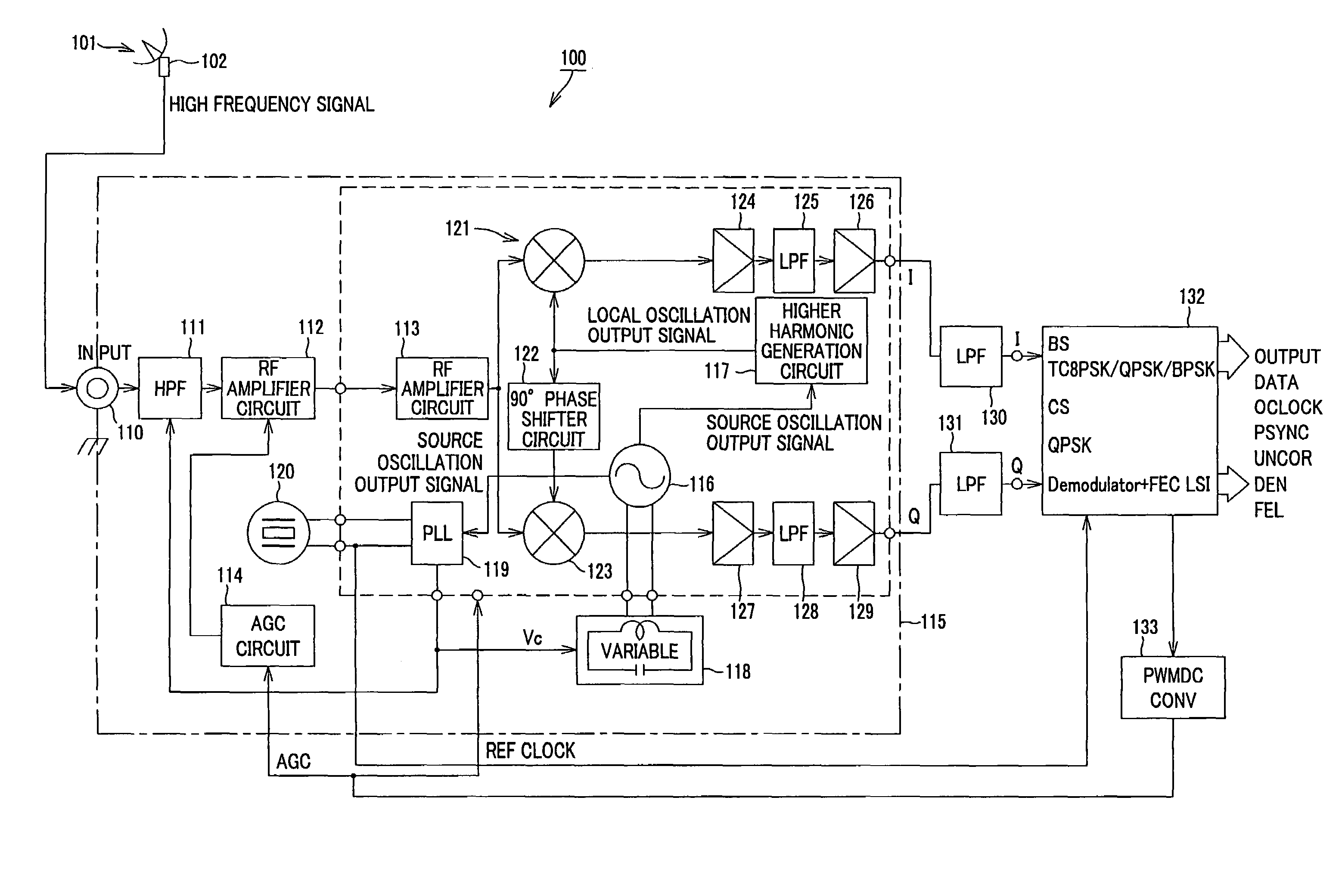
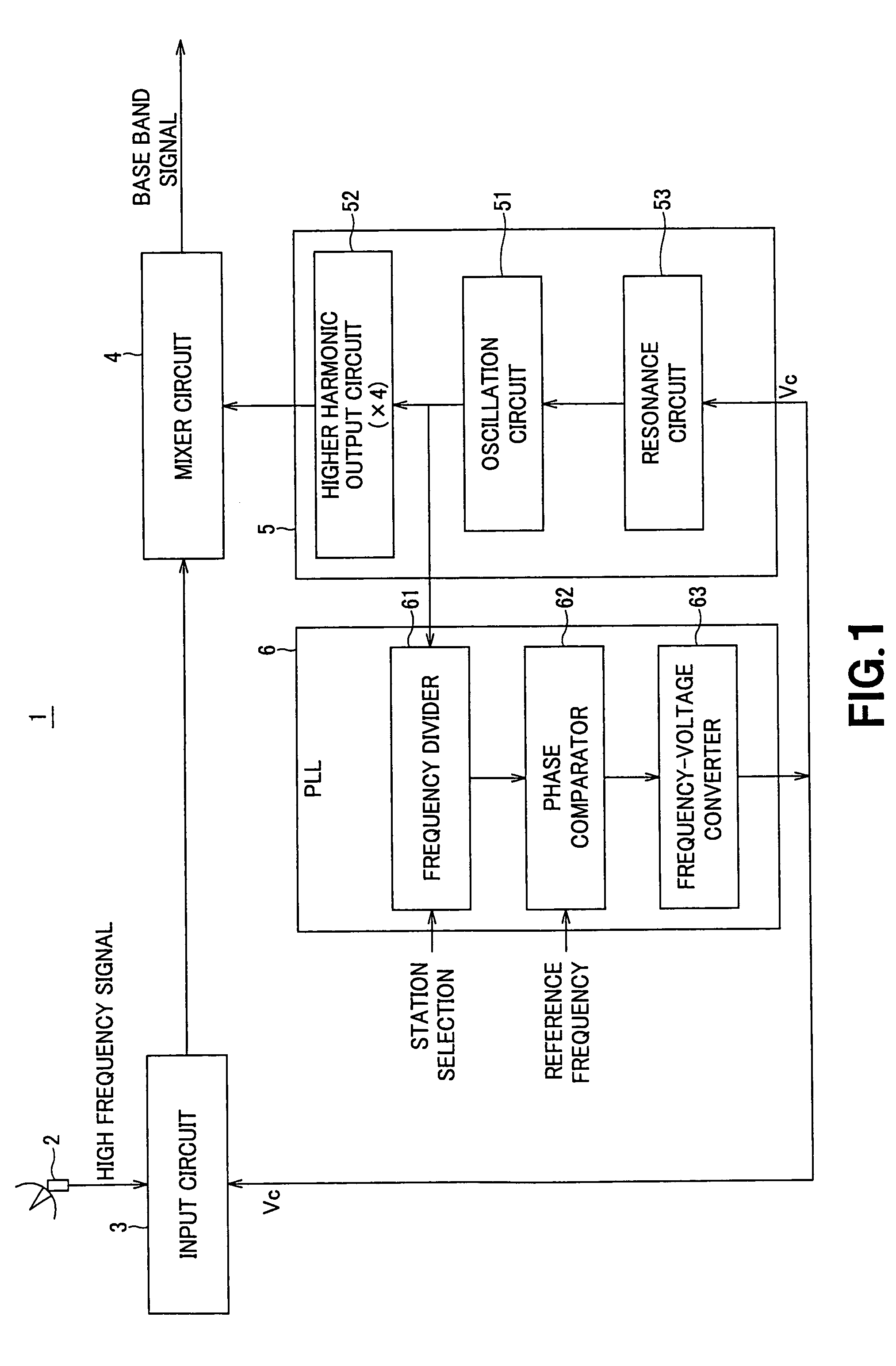
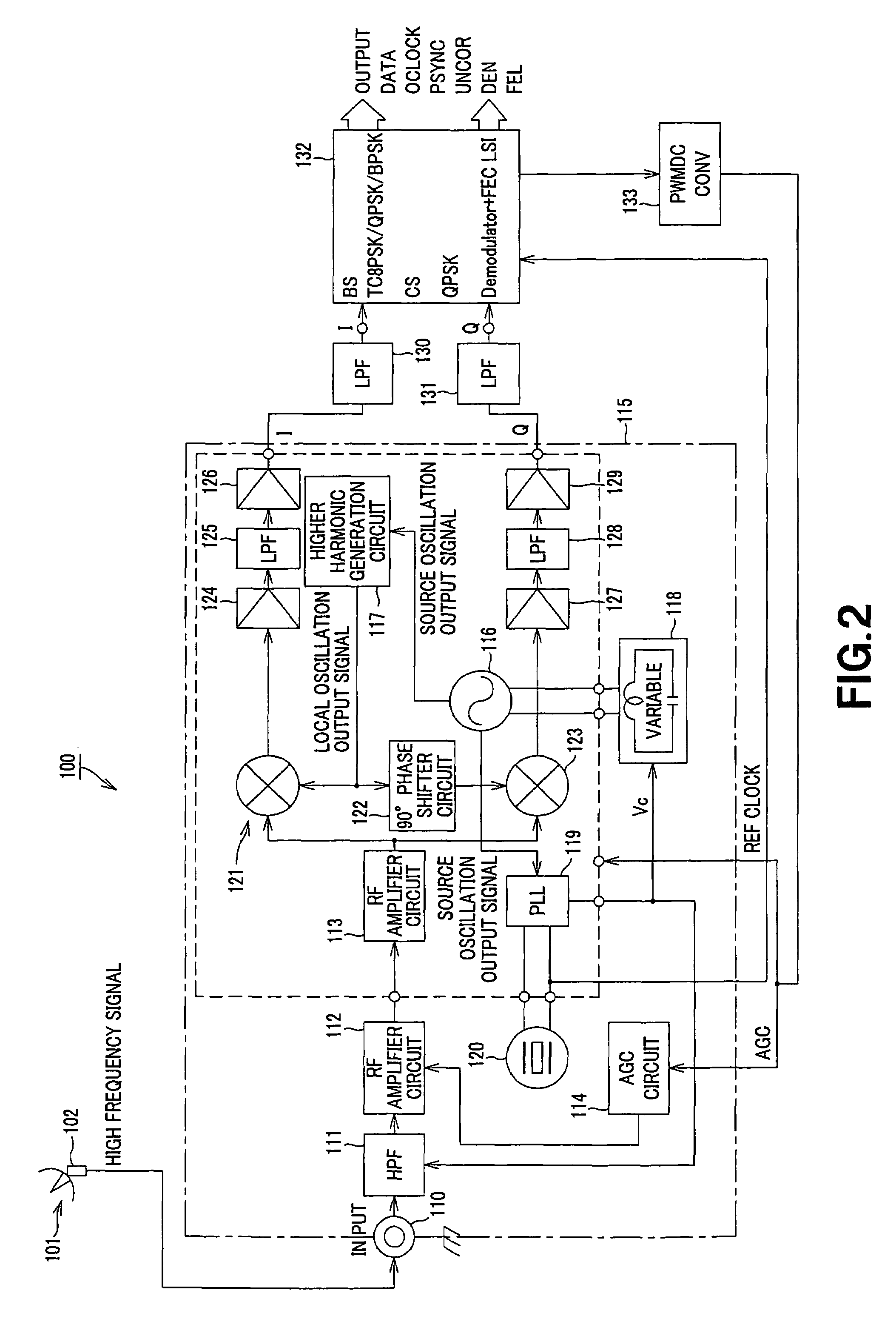
[0021]Now, the present invention will be described in greater detail by referring to the accompanying drawings that schematically illustrate an embodiment of the invention, which is a high frequency signal receiving circuit 1. The high frequency signal receiving circuit 1 of FIG. 1 is a direct conversion type high frequency signal receiving circuit adapted to receive a high frequency signal of 1 to 2 GHz band obtained from a digital broadcast signal of about 12 GHz band transmitted from a broadcasting satellite (to be referred to as BS hereinafter) or a 110° communications satellite (to be referred to as CS hereinafter) and frequency-convert it into a base band signal. The high frequency signal receiving circuit can directly down-convert an RF signal input to it by way of an antenna into a base band signal by inputting the target broadcasting channel frequency into a mixer circuit as local oscillation output signal without converting the RF signal into an intermediate frequency sign...


PUM


Abstract

A high frequency signal receiver can prevent higher harmonics other than a necessary higher harmonic from being subjected to frequency conversion so as to interfere with the base band signal in a broadcasting channel frequency band. The receiver has a high frequency signal receiving circuit 1 that comprises an input circuit 3 to which a high frequency signal (RF signal) subjected to frequency conversion from a 12 GHz band to a 1 to 2 GHz band is input, a mixer circuit 4 adapted to frequency convert the signal of 1 to 2 GHz band output from the input circuit 3 into a base band signal, a local oscillation output circuit section 5 adapted to supply a signal of a frequency band to be mixed with the signal output of the input circuit 3 to the mixer circuit 4 and a PLL circuit section 6 to which the source oscillation output signal from the local oscillation output circuit section 5 is input. The local oscillation output circuit section 5 has an oscillation circuit 51, a higher harmonic output circuit 52 that generates the fourth harmonic of the output signal of the oscillation circuit 51 and a resonance circuit 53. It controls both the resonance frequency of the resonance circuit 53 of the local oscillation output circuit section 5 and the frequency characteristic of the input circuit 3 by means of the control voltage output from the PLL circuit section 6 so as to boost the higher harmonic of an order that corresponds to desired broadcasting channel frequency and attenuate higher harmonics of all other orders that appear in other frequency bands that overlap the broadcasting channel frequency in the input circuit 3.

Description

BACKGROUND OF THE INVENTION[0001]1. Field of the Invention[0002]This invention relates to a high frequency signal receiver to be typically installed in a tuner of a television receiving set.[0003]This application claims the priority of the Japanese Patent Application Nos. 2003-173822 filed on Jun. 18, 2003 and 2004-146917 filed on May 17, 2004, the entirety of which is incorporated by reference herein.[0004]2. Related Background Art[0005]As a radio wave for digital broadcasting using a broadcasting satellite (to be referred to as BS hereinafter) or a communications satellite (to be referred to as CS hereinafter) is received by a parabolic antenna, it is converted into a high frequency signal (RF signal) of 1 to 2 GHz and then the signal is sent to the high frequency signal receiver of a so-called set top box or tuner having a functional feature of receiving satellite broadcasting. The high frequency signal receiver is provided with a frequency converter for down-converting the RF si...

Claims


Application Information

Patent Timeline
Patent Type & Authority Patents(United States)
IPC IPC(8): H04B1/26H04N7/20H03D7/16H03J3/18H03J3/24H03L7/18H04B1/10H04B1/18H04B1/30H04B15/06H04L27/14H04N5/208H04N21/647
CPCH03J3/24H03L7/0805H03L7/18H04B1/18H03D7/165H03J3/185H04N5/208
Inventor SHIMANUKI, MASARU
Owner SONY CORP
Why Eureka
Try Eureka