Fastening tool and fastening bolt
a technology of fastening tool and fastening bolt, which is applied in the direction of washers, rod connections, screws, etc., can solve the problems of prone to loosening of the fastened portion, and insufficient fastening force of the fastening bolt, etc., to achieve convenient fixing to each other, large displacement load, and sufficient fastening for
- Summary
- Abstract
- Description
- Claims
- Application Information
AI Technical Summary
Benefits of technology
Problems solved by technology
Method used
Image
Examples
embodiment 1
[0035]A fastening tool of an embodiment 1 of the present invention will be explained.
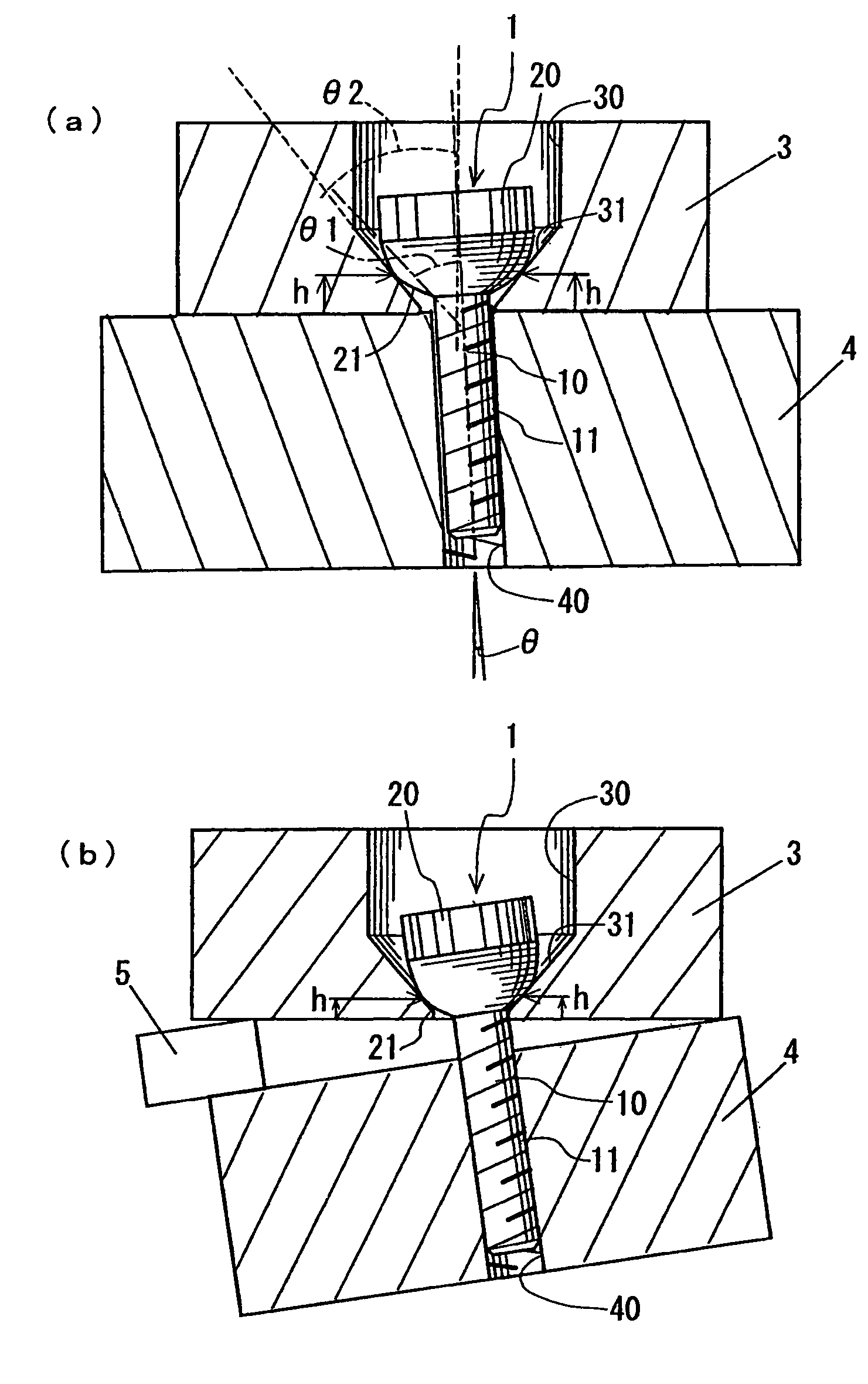
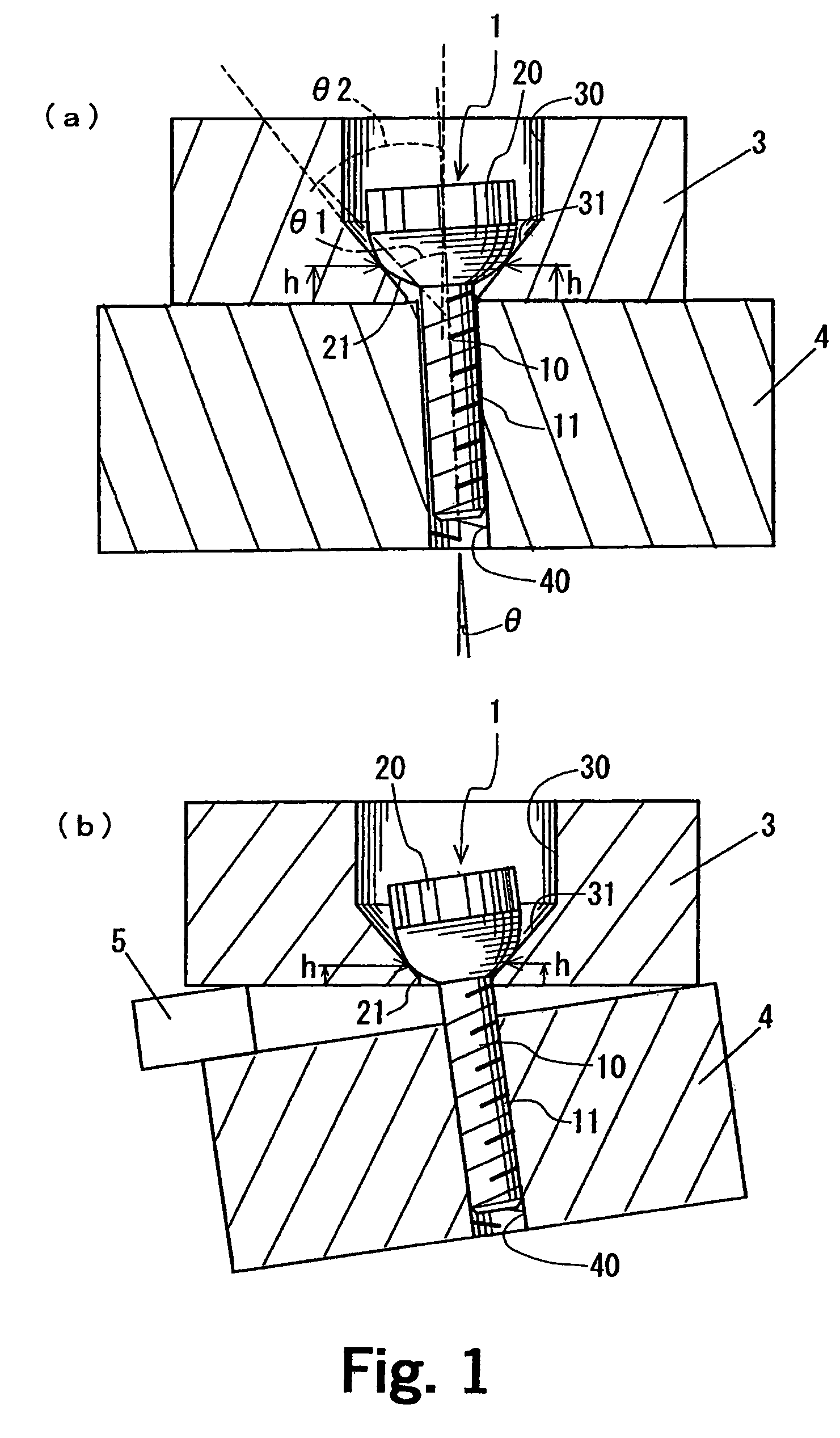
[0036]As shown in FIG. 1(a), this fastening tool includes a first member 3 having a bolt through hole 30 and a tapered seat surface 31, a second member 4 having a threaded hole 40, and a fastening bolt 1 for fastening the members 3 and 4.
[0037]The fastening bolt 1 includes a rod-like bolt body 10 provided at its outer periphery with a male thread 11, and a cylindrical head 20 which is provided on an end of the bolt body 10 and which has a diameter larger than that of the bolt body 10. An upper surface of the head 20 of the fastening bolt 1 has a hexagonal hole (see FIG. 2) into which a hexagonal wrench is to be fitted. A side surface of the head 20 is knurled. A lower surface of the head 20 is tapered toward a tip end of the bolt body 10 such that its diameter is reduced toward the tip end of the bolt body 10, and is a tapered curved surface 21 in which the tapered surface outwardly swells in a form...
embodiment 2
[0050]A shaft coupling of an embodiment 2 as a fastening tool of the invention will be explained.
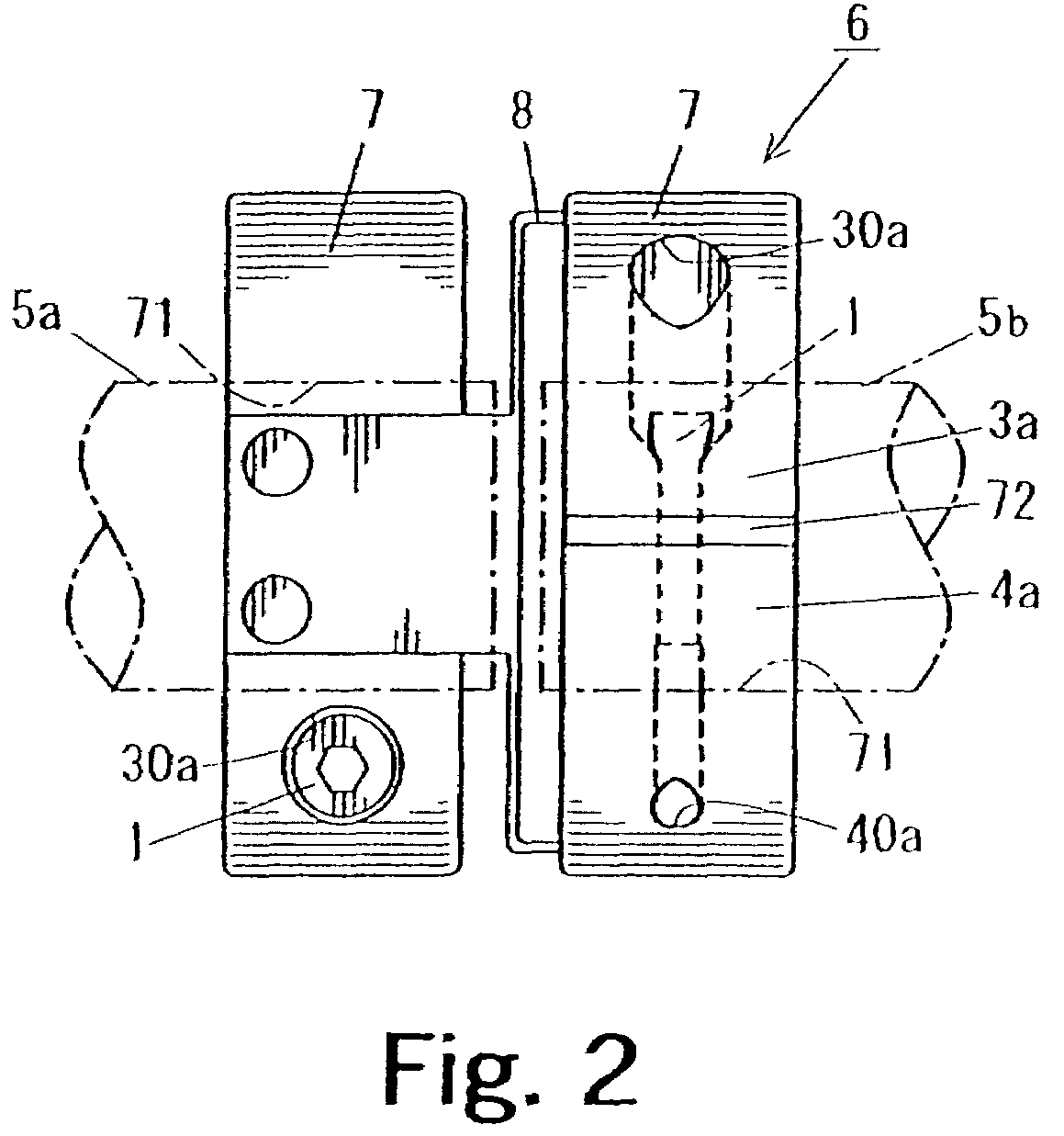
[0051]As shown in FIG. 2, in the shaft coupling 6, two C-shaped fastening bodies 7 provided with a slot groove 72 extending to a center shaft hole 71 are connected to each other by means of a leaf spring intermediate body 8. A shaft 5a which is a driving shaft is disposed in one of the fastening bodies 7, and another shaft 5b which is a follower shaft is disposed in the other fastening body 7. With this structure, the two shafts 5a and 5b are connected to each other through the shaft coupling 6.
[0052]As shown in FIG. 3(a), in the fastening body 7, the one of the opposed ends 3a (first member 3) of the slot groove 72 is provided with the bolt through hole 30, and the other end 4a (second member 4) is provided with the threaded hole 40a into which the fastening bolt 1 is to be threadedly inserted. The bolt through hole 30a is provided with a tapered seat surface 31a whose diameter is incre...
embodiment 3
[0056]Another shaft coupling as a fastening tool of an embodiment 3 of the present invention will be explained.
[0057]As shown in FIG. 4, a fastening bolt 1a used in a shaft coupling 6c, a lower surface of the head 20a is formed as a tapered curved surface 21a and is substantially aligned with a bolt through hole 30a of the fastening body 7 and is sunk. That is, the lower surface of the head 20a of the fastening bolt 1a is formed as the tapered curved surface 21a whose diameter is reduced toward a tip end of the bolt body 10, but the lower surface is not formed with the tapered curved surface 21 unlike the embodiment 1. The fastening body 7c of the shaft coupling 6c is provided with an auxiliary groove 13 in the axial direction at location opposed to the slot groove 72 of the shaft hole 71. The auxiliary groove 13 allows the diameter of the fastening body 7c to be reduced smoothly. Other structure is the same as that of the embodiment 2, the same symbols as those in FIGS. 2 and 3(a) ...
PUM
 Abstract
Description
Claims
Application Information
 - R&D
- Intellectual Property
- Life Sciences
- Materials
- Tech Scout
- Unparalleled Data Quality
- Higher Quality Content
- 60% Fewer Hallucinations
Browse by: Latest US Patents, China's latest patents, Technical Efficacy Thesaurus, Application Domain, Technology Topic, Popular Technical Reports.
© 2025 PatSnap. All rights reserved.Legal|Privacy policy|Modern Slavery Act Transparency Statement|Sitemap|About US| Contact US: help@patsnap.com


