
Network revision system with local system ports

a network revision system and local system technology, applied in the field of network revision system with local system ports, can solve the problems of increasing the presence and severity of spaghetti cabling, and increasing the difficulty of tracking a single cable from end to end in the lan

Inactive Publication Date: 2008-05-06
PANDUIT
View PDF46 Cites 135 Cited by
  • Summary
  • Abstract
  • Description
  • Claims
  • Application Information

AI Technical Summary

Benefits of technology

The invention is a revision system for a network that allows data ports to be connected to each other for communication. The system includes a computer processor, a scanner, and a port plate for each data port. The scanner can polling the data ports to determine their connective status. The system also includes a portable information module that can be connected to the local system ports for displaying information about the data ports. The technical effect of the invention is to provide an efficient and effective way to revise and connect data ports in a network.

Problems solved by technology

As the density and volume of needed cabling has increased, “spaghetti” cabling, a term colorfully describing a dense, chaotic arrangement of cables and the resultant difficulty of tracking a single cable from end to end in the LAN, has correspondingly become more commonplace and more problematic.
This purpose is being significantly thwarted by the increased presence and severity of spaghetti cabling, particularly when larger LANs are involved.
Under a manual documentation scheme, when changes were needed in a particular LAN configuration, the operator would be faced with the complex problem of determining whether and which cords needed to be added, removed, or transferred (re-routed on one end).
The problem became even more complex when the order of such steps needed to be considered, i.e., which cord to change before which other cord.
The problem became still more complex when one considered cord length issues.
Assuming the LAN operator even kept accurate records about the length of cord used to maintain particular connections within the LAN, there would still be the formidable task of determining whether a particular cord was sufficiently long, for example, to be moved from a particular port on one network rack to a different port on another network rack.
For example, if electronic network equipment malfunctions, critical communications could be interrupted, necessitating rapid connection of a destination to a new source, which, in turn, requires a rapid change in the LAN cabling.
If a cabling revision step is made incorrectly, it could disrupt vital communications.
In addition, given the high cost of technically skilled labor, employing an operator and one or more revisors to sporadically or continuously monitor and reconfigure a LAN, can be very costly.
Thus, trying to efficiently reconfigure these spaghetti cable networks has become very complex, very time consuming, very confusing, and very costly.
Given the high density of data ports in current networks and the usual need for a reconfiguration to be performed quickly, the rate of revisor error is significant.
Of course, a cord that is too short will result in a failed effort to make the connection, thereby wasting expensive time; a cord that is too long will produce wasteful slack that contributes to spaghetti cabling.
Because the cord is considered removed upon the removal of its first end, however, the two lights are both turned off at this point, thereby making it very difficult for the revisor to find the other end of the cord, particularly if the length of the cord is partially or totally hidden.
Sometimes, such a procedure would result in the inefficient unplugging of a cord end from a port only to have the same end immediately reinserted into the same data port in the subsequent step.
Thus, additions, removals, and transfers still can be very cumbersome with current electronic systems and have much inefficiency existent in current procedures.

Method used


Image

  • Network revision system with local system ports
  • Network revision system with local system ports
  • Network revision system with local system ports

Examples


Embodiment Construction

[0023]The invention is directed to apparatus and methods for facilitating the efficient maintenance and / or reconfiguration of a LAN using a system which includes an automatic direction and response system and a scanner system.

[0024]The complete disclosures of the previously filed provisional patent applications Ser. Nos. 60 / 252,517 filed Nov. 22, 2000; 60 / 257,396 filed Dec. 22, 2000; 60 / 270,811 filed Feb and No. 60 / 297,289 filed Jun. 11, 2001 are incorporated herein by reference.

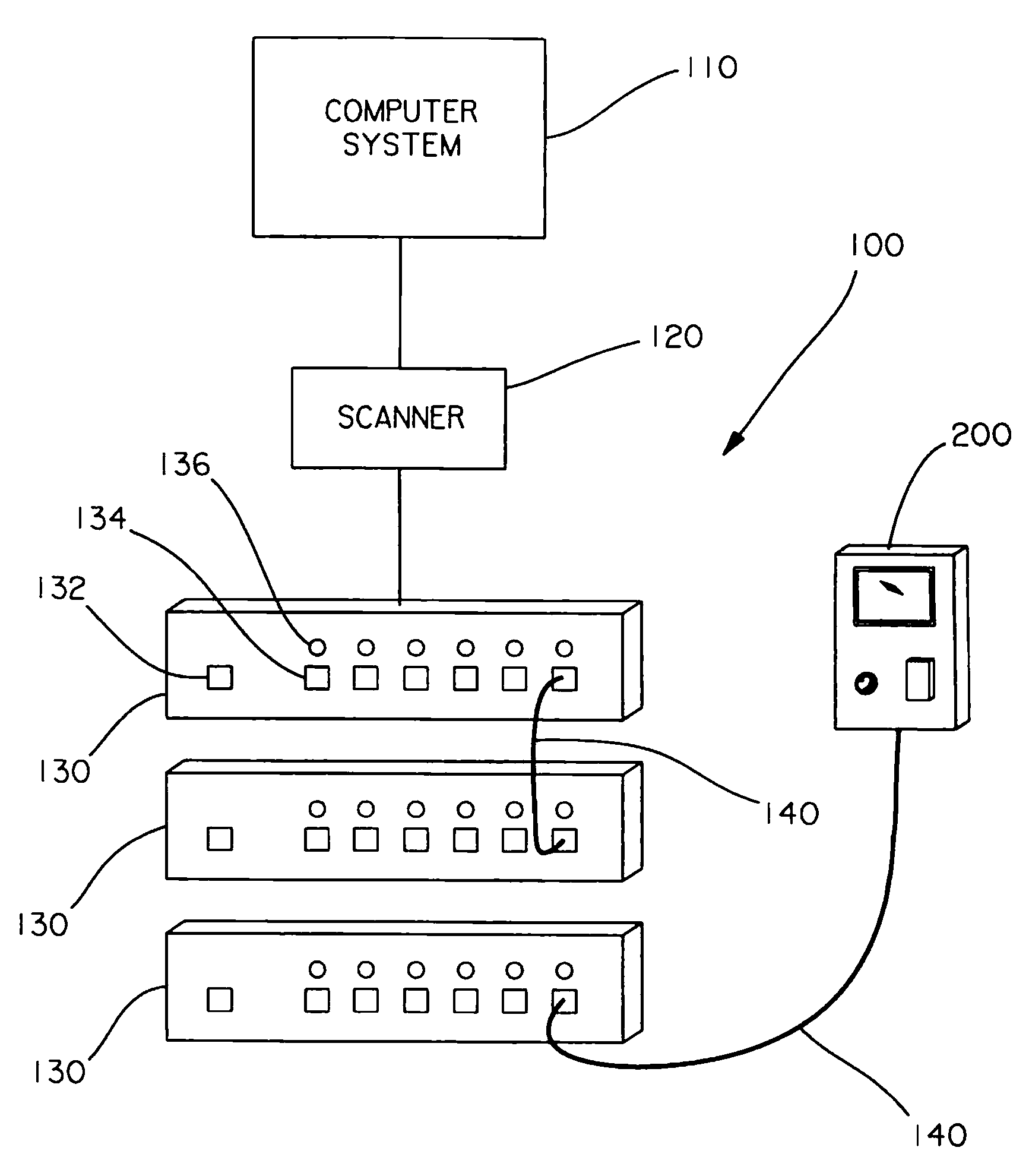
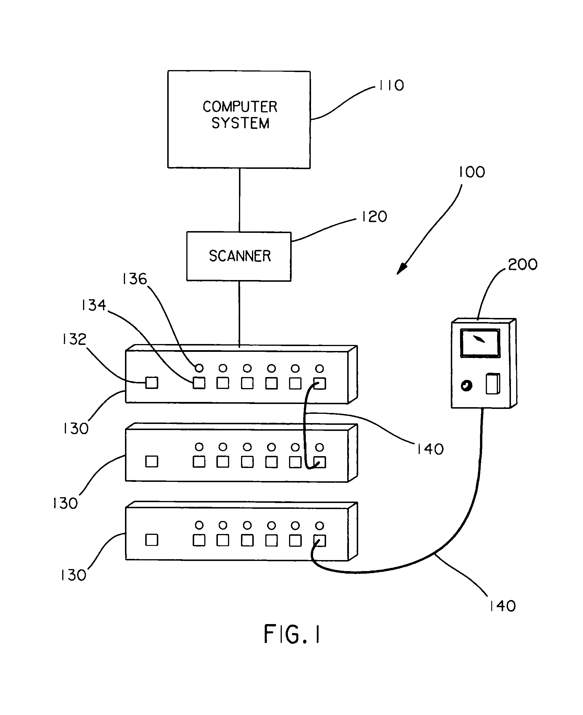
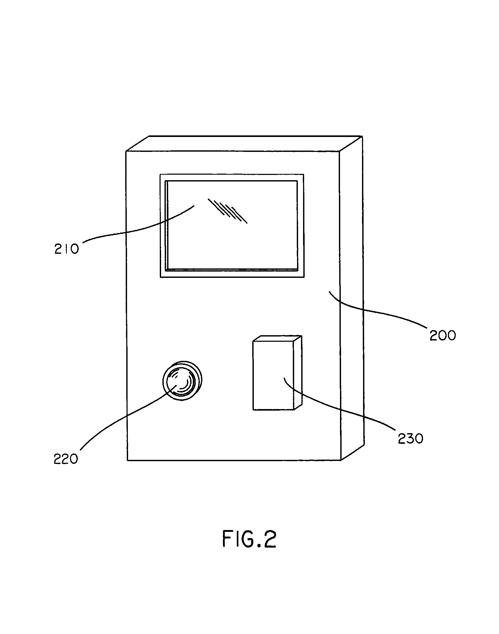
[0025]The LAN 100, as shown in FIG. 1, may include a scanner 120, an optional information module 200, a number of network racks 130 having arrays of data ports 134 interconnected by a large number of cords 140, LEDs 136 adjacent to tile data ports 134, and a multitude of system ports 132 for connection to the system. Like other LAN reconfiguration direction and response systems, instructions for reconfiguring the LAN are determined and communicated by a computer system 110 or the like which controls the LAN....


PUM


Abstract

A revision system for a network having a plurality of data ports, pairs of the data ports being connectable by a patch cord to place the pairs of data ports into communication with each other, the revision system including a computer processor, a scanner in communication with the computer processor, the scanner capable of polling at least some of the data ports for determining connective status information therefrom, a plurality of local system ports disposed at distinct physical locations within the system, the local system ports in communication with the computer processor, and a portable information module for connecting to respective ones of the plurality of local system ports, whereby when the portable information module is connected to one of the local system ports, the portable information module may be placed into communication with and display information about respective ones of the data ports in the system.

Description

RELATED APPLICATION[0001]This application is claiming priority to the following previously filed U.S. provisional patent applications: Ser. Nos. 60 / 252,517 filed Nov. 22, 2000; 60 / 257,396 filed Dec. 22, 2000; No. 60 / 270,811 filed Feb. 23, 2001; and 60 / 297,289 filed Jun. 11, 2001; the entirety of the previously filed applications being incorporated herein by reference.BACKGROUND OF THE INVENTION[0002]As communication network utilization and technology continues to escalate, the typical local area network (LAN) is simultaneously growing larger and denser, resulting in an exponential growth in the number of cord connections needed between ports in respective patch panels, communication switches, equipment, etc., to maintain appropriate network functionality. Each such connection typically entails a cord (cable) of suitable type connecting a pair of jacks, adapters, or other connector ports in the network. Sometimes the connected ports are only inches apart; other times, the ports are d...

Claims


Application Information

Patent Timeline
Patent Type & Authority Patents(United States)
IPC IPC(8): G06F15/173H01R3/00H01R9/05H01R11/18H04L12/24H04L12/26H04M3/22H04Q1/14
CPCH04L12/2602H04L43/00H04Q1/136H01R11/18H04L41/0813H04L43/0817H04M3/229H04Q1/144H04Q2201/802H01R24/62
Inventor CAVENEY, JACK E.
Owner PANDUIT
Learn More