
Hub assembly for disk brake of bicycle

a technology for bicycle disc brakes and hubs, which is applied in the direction of braking discs, cycle equipments, bicycle brakes, etc., can solve the problems of decreasing the lifetime of the hub assembly, and achieve the effect of reducing the disadvantage and/or obviating the disadvantag

Active Publication Date: 2008-05-06
MING CYCLE INDAL
View PDF9 Cites 13 Cited by
  • Summary
  • Abstract
  • Description
  • Claims
  • Application Information

AI Technical Summary

Benefits of technology

Prevents stress concentration on inserts, enhancing the hub assembly's lifetime and facilitating rapid assembly and disassembly of the brake disk.

Problems solved by technology

Thus, the inserts 66 of the urging cap 65 are easily worn or broken due to a stress concentration, thereby decreasing the lifetime of the hub assembly.

Method used


Image

  • Hub assembly for disk brake of bicycle
  • Hub assembly for disk brake of bicycle
  • Hub assembly for disk brake of bicycle

Examples


Embodiment Construction

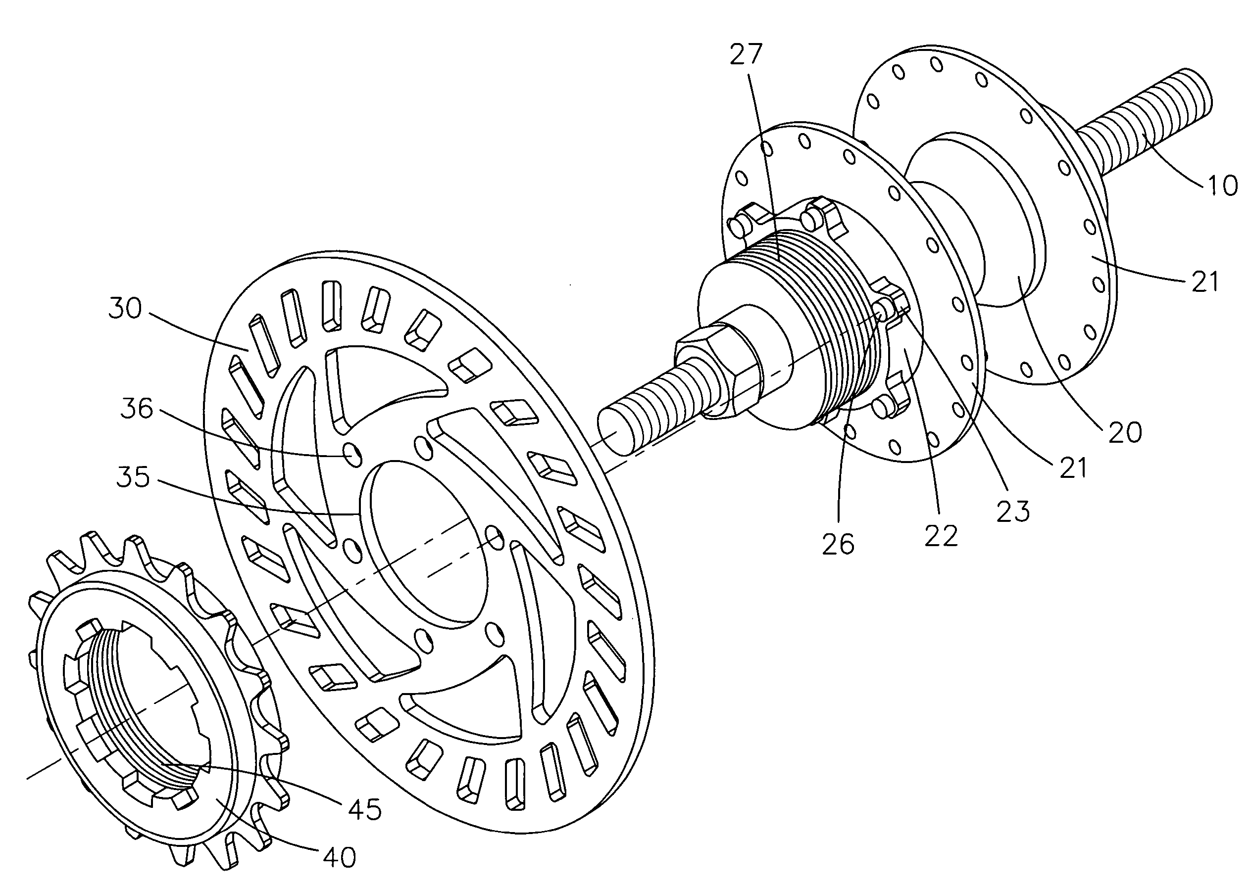
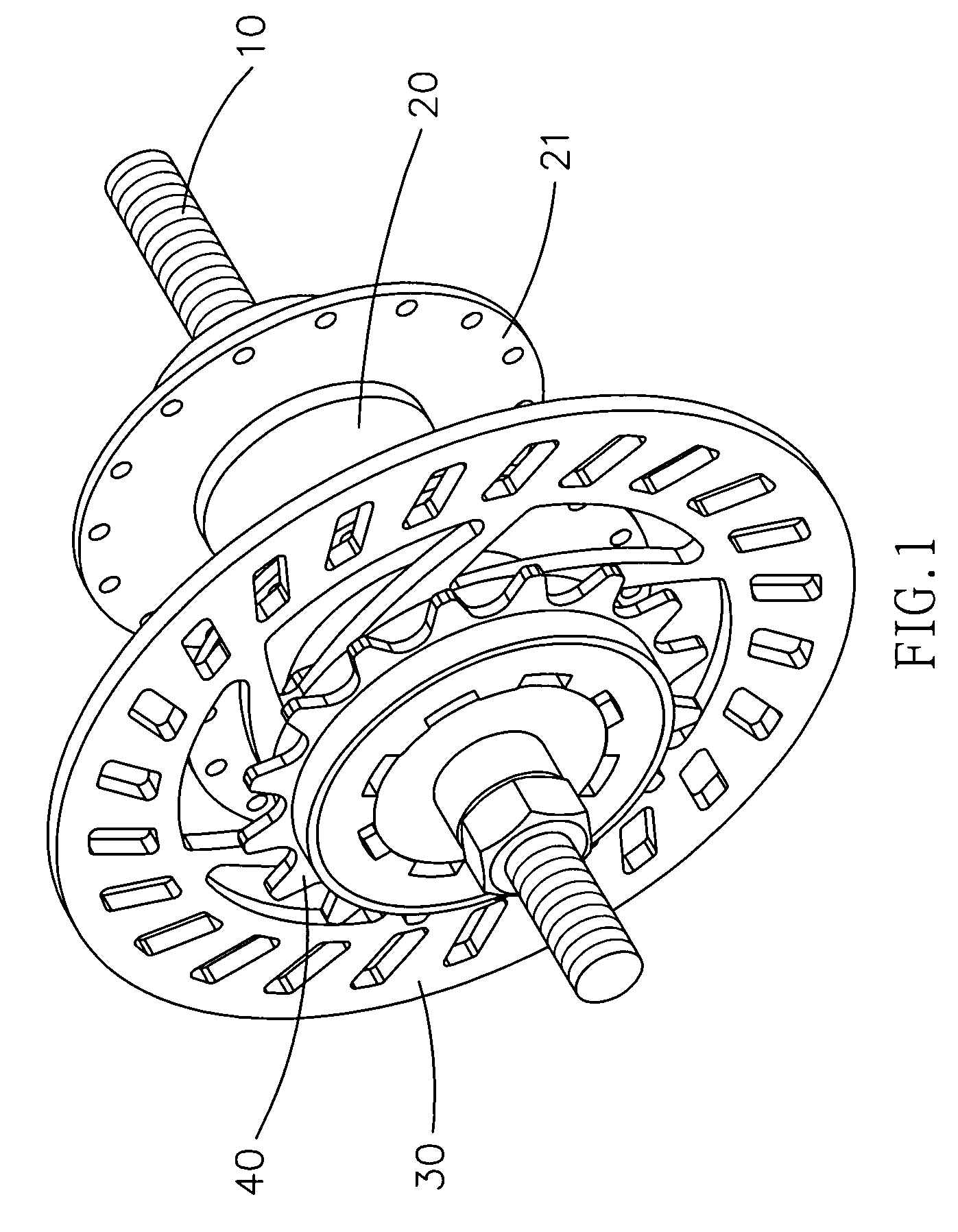
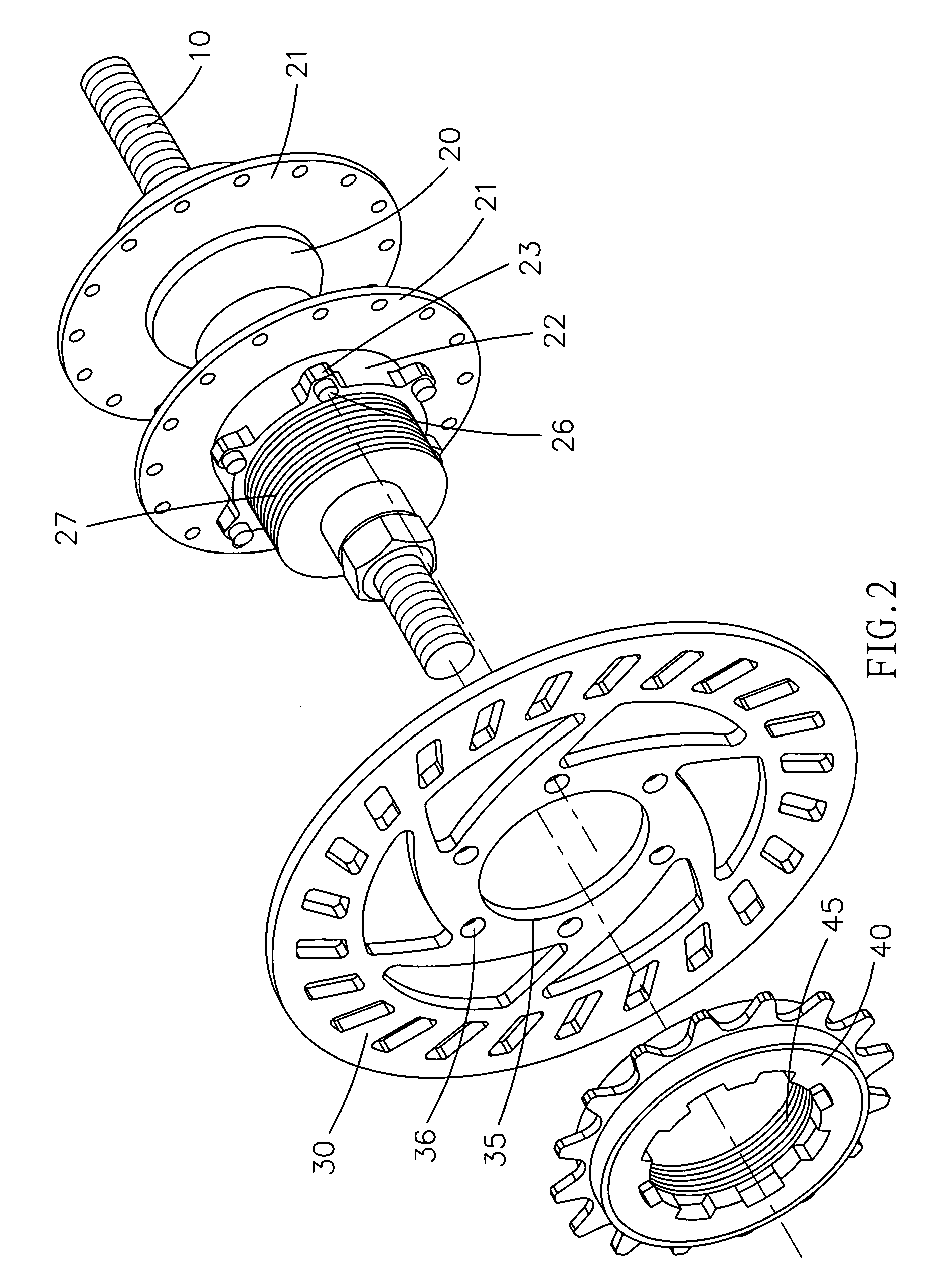
[0019]Referring to the drawings and initially to FIGS. 1-3, a hub assembly for a disk brake of a bicycle in accordance with the preferred embodiment of the present invention comprises a support shaft 10 secured to a seat stay or chain stay (not shown), a hub body 20 pivotally mounted on the support shaft 10 and provided with two opposite drum disks 21 for mounting spokes (not shown), a mounting portion 22 mounted on and protruding from a side of one of the two drum disks 21 of the hub body 20, a threaded section 27 mounted on and protruding from an end face of the mounting portion 22, a brake disk 30 mounted on the threaded section 27 and having a first side resting on the end face of the mounting portion 22, and a chainwheel 40 screwed onto the threaded section 27 and pressing a second side of the brake disk 30 so that the brake disk 30 is clamped between the mounting portion 22 and the chainwheel 40.

[0020]The mounting portion 22 has a substantially circular shape. The end face of ...


PUM


Abstract

A hub assembly for a disk brake of a bicycle includes a support shaft, a hub body pivotally mounted on the support shaft and provided with two drum disks, a mounting portion protruding from one of the drum disks, a threaded section protruding from the mounting portion, a brake disk resting on the end face of the mounting portion, and a chainwheel screwed onto the threaded section and pressing the brake disk so that the brake disk is clamped between the mounting portion and the chainwheel closely. Thus, the brake disk is mounted on and detached from the hub body by screwing and unscrewing the chainwheel, so that the hub assembly is assembled and disassembled easily and rapidly, thereby facilitating a user assembling and disassembling the hub assembly.

Description

BACKGROUND OF THE INVENTION[0001]1. Field of the Invention[0002]The present invention relates to a hub assembly, and more particularly to a hub assembly for a disk brake of a bicycle.[0003]2. Description of the Related Art[0004]A conventional hub assembly for a disk brake of a bicycle in accordance with the prior art shown in FIGS. 6 and 7 comprises a support shaft 50 secured to a seat stay or chain stay (not shown), a hub body 60 pivotally mounted on the support shaft 50 and provided with two drum disks 61 for mounting spokes (not shown), a chainwheel 80 mounted on one of the two drum disks 61 of the hub body 60, a mounting portion 62 protruding from the other one of the two drum disks 61 of the hub body 60 and having a periphery provided with a plurality of protruding blocks 63 each formed with an insertion hole 64, a brake disk 70 mounted on the mounting portion 62 and having a periphery provided with a plurality of protruding plates 75 each resting on the respective protruding b...

Claims


Application Information

Patent Timeline
Patent Type & Authority Patents(United States)
IPC IPC(8): B62L1/00B62D27/06
CPCB60B27/0052B60B27/023F16D65/12F16D2065/1384F16D2065/1392
Inventor CHANG, CHUNG MING
Owner MING CYCLE INDAL
Learn More