
Digital-to-analog converter

a digital converter and analog technology, applied in the field of digital-to-analog converters, can solve the problems of large number of signal lines, significant distortion of output voltage, and increase in resistor string number and the number of switches needed to select the divided voltage, so as to reduce parasitic loads and improve accuracy

Active Publication Date: 2008-04-29
LAPIS SEMICON CO LTD
View PDF6 Cites 7 Cited by
  • Summary
  • Abstract
  • Description
  • Claims
  • Application Information

AI Technical Summary

Benefits of technology

This design significantly reduces the number of circuit elements and improves accuracy by confining the midrange to the linear part of the gamma curve, allowing for more consistent and efficient generation of output levels with reduced space occupation.

Problems solved by technology

A problem with the conventional DACs described above is that the number of resistors in the resistor string and the number of switches needed to select the divided voltages increase exponentially.
This is a particular problem nowadays, because the increasing size of liquid crystal displays demands a gray scale with more levels for a more vivid color display.
Another problem is posed by the large number of signal lines or ‘channels’ that are driven through separate switching circuits from single resistor string.
In such cases, the combined effect of parasitic wiring resistance or parasitic circuit elements concentrated at a single point in the resistor string can significantly distort the output voltages.
In the two-stage nonlinear DAC described above, accuracy is a particular problem near the upper and lower reference voltage levels, where the gray scale is nonlinear and the voltage differences between adjacent gray levels gradually increase, demanding a gamma correction that the second-stage converter cannot provide.

Method used


Image

  • Digital-to-analog converter
  • Digital-to-analog converter
  • Digital-to-analog converter

Examples


Embodiment Construction

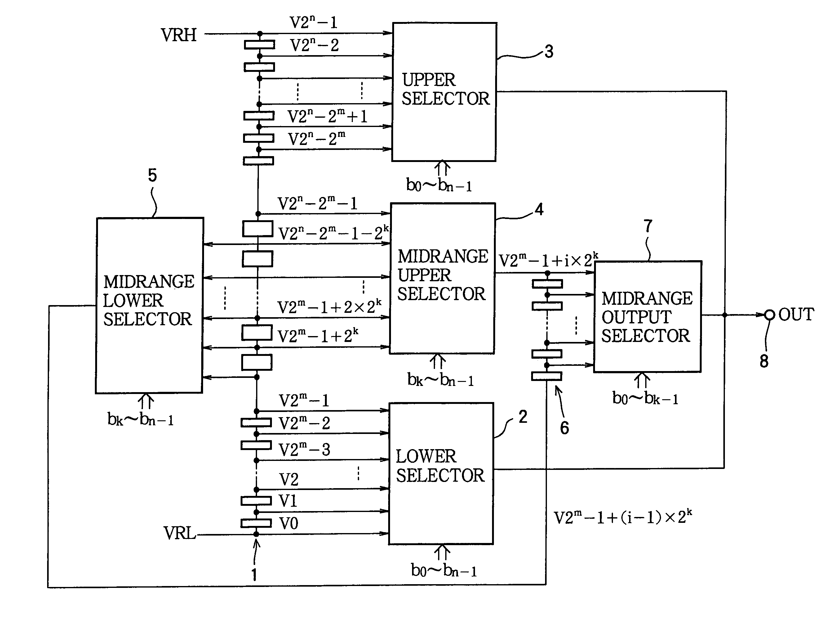
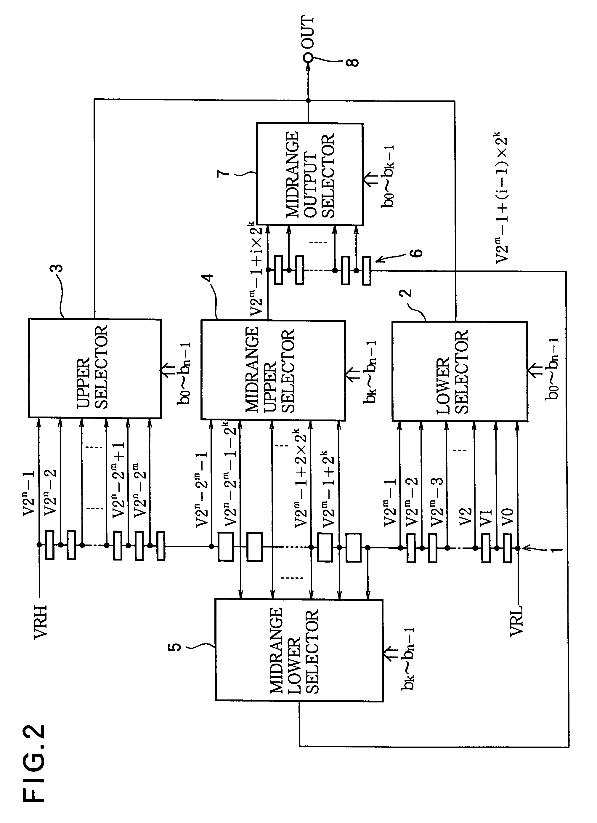
[0025]A DAC embodying the present invention will now be described with reference to the attached drawings, in which like elements are indicated by like reference characters. For simplicity, parentheses are omitted in the drawing: for example, V(2n−1) is shown in the drawings as V2n−1.

[0026]Referring to FIG. 2, the DAC converts an n-bit digital input signal taking values from 0 to 2n−1 to an analog output voltage taking values from VRL to VRH. The parameter n is a positive integer, and VRH and VRL are externally supplied analog reference voltages. The analog output voltage, also referred to below as a driving voltage or gray scale voltage, can be used to drive a picture element in a display device. The DAC comprises a resistor string 1 consisting of a plurality of resistors connected in series between the lower reference voltage VRL and the upper reference voltage VRH to function as a voltage divider; a lower selector 2, an upper selector 3, a midrange upper selector 4, and a midrang...


PUM


Abstract

An analog-to-digital converter has a resistor string that generates a series of voltages that are equally spaced in the middle range of the series and unequally spaced at the upper and lower ends. An upper selector selects voltages at the upper end. A lower selector selects voltages at the lower end. A pair of midrange selectors select a pair of adjacent voltages in the middle range. A midrange voltage generator generates further voltages equally spaced between the two selected midrange voltages. An output selector selects one of the further voltages. The selectors are controlled by various bits of a digital input signal. The voltage selected by the upper selector, lower selector, or output selector becomes an analog output signal. This analog-to-digital converter has comparatively few resistors and transistors and can generate accurate voltages for driving a gray-scale display.

Description

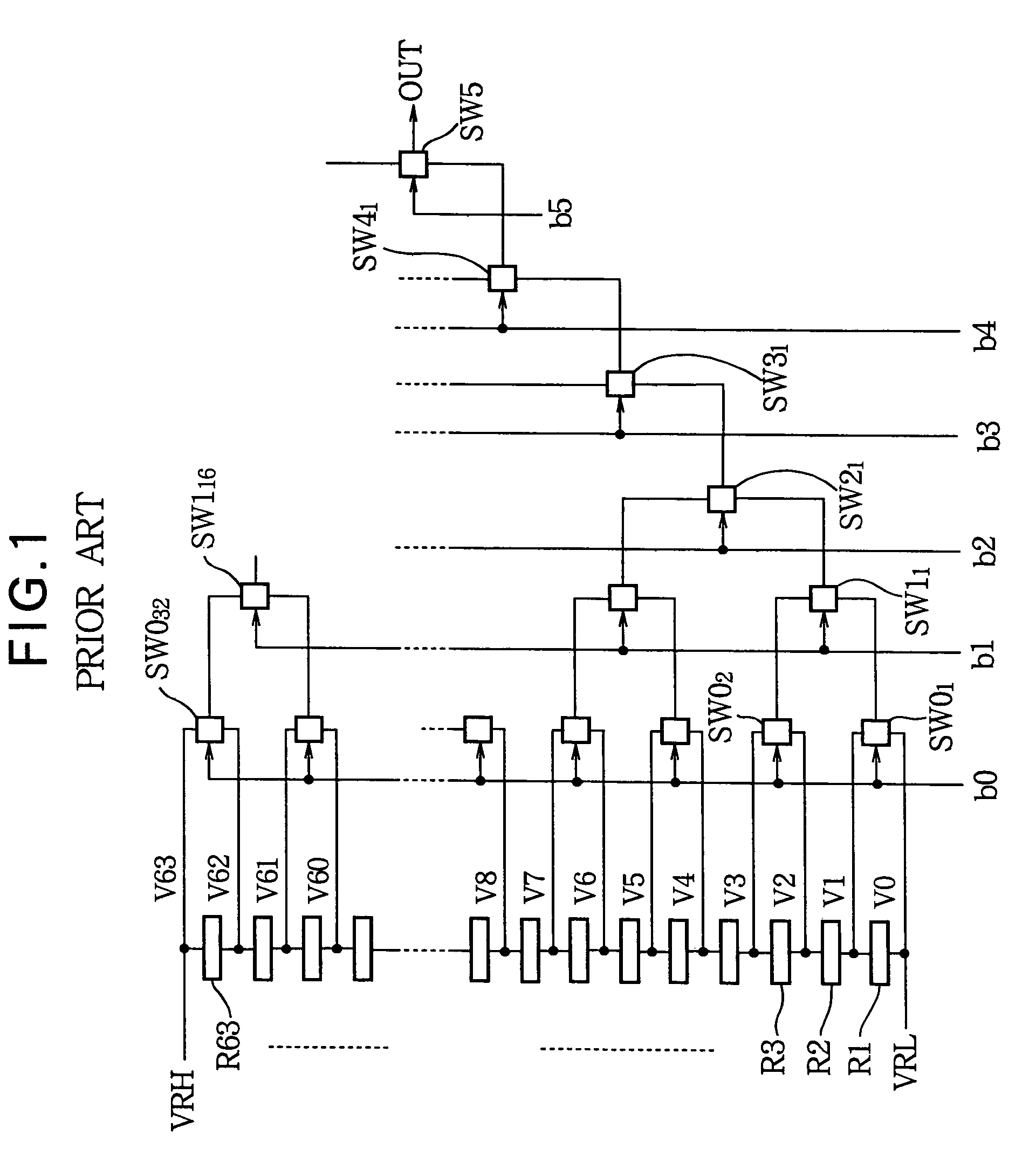
BACKGROUND OF THE INVENTION[0001]1. Field of the Invention[0002]The present invention relates to a digital-to-analog converter (DAC) that generates voltages useful for driving, for example, a liquid crystal to produce a vivid display.[0003]2. Description of the Related Art[0004]Referring to FIG. 1, a conventional DAC of the type used in a liquid crystal driving circuit to convert a six-bit digital signal to an analog voltage signal with sixty-four levels comprises a resistor string that divides a reference voltage and outputs sixty-four different voltages, and a switching circuit that selects one of the sixty-four voltages according to the value of the digital input signal.[0005]The resistor string is a string of sixty-three resistors (R1 to R63) connected in series between a lower reference voltage VRL and an upper reference voltage VRH to form a voltage divider. Voltages V0 (=VRL), V1, V2, . . . , V63 (=VRH) at sixty-four different levels are output from the two ends and sixty-two...

Claims


Application Information

Patent Timeline
Patent Type & Authority Patents(United States)
IPC IPC(8): H03M1/66
CPCH03M1/76H03M1/66
Inventor LAN, SHIMING
Owner LAPIS SEMICON CO LTD
Learn More