Vehicle headlamp
a headlamp and projector technology, applied in fixed installation, lighting and heating equipment, transportation and packaging, etc., can solve the problems of insufficient brightness of the diffusing region of the light distribution pattern, inability to control the brightness of the irradiated light with high precision, and the optical axis side region cannot be effectively utilized for light distribution control, etc., to achieve high precision, increase the amount of light, and sufficient brightness
- Summary
- Abstract
- Description
- Claims
- Application Information
AI Technical Summary
Benefits of technology
Problems solved by technology
Method used
Image
Examples
second embodiment
[0085]Next, description will be given to the invention.
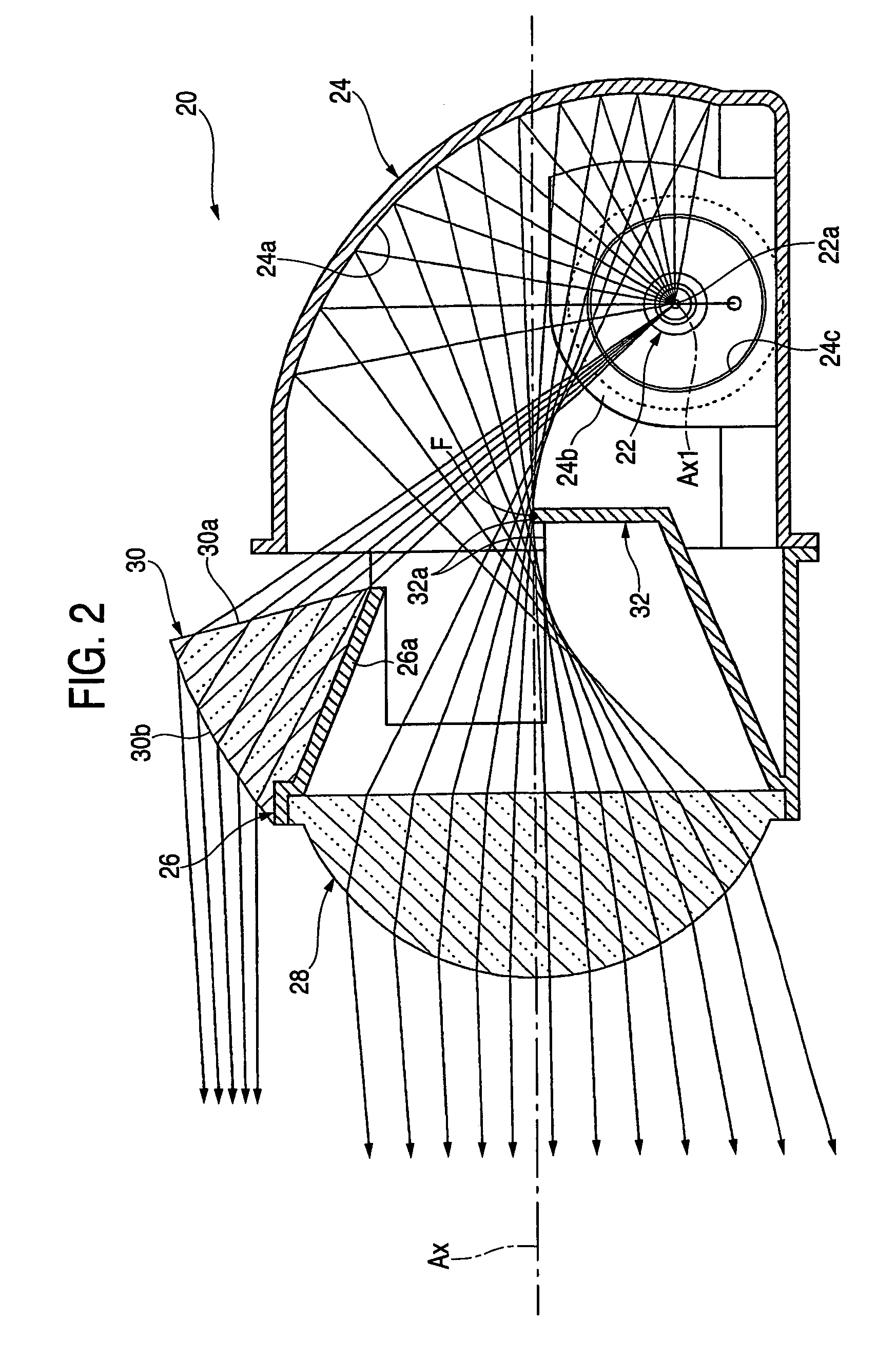
[0086]FIG. 6 is a sectional side view showing, as a single unit, a lighting unit 120 of a vehicle headlamp according to the embodiment.
[0087]As shown in FIG. 6, the basic structure of the lighting unit 120 is entirely the same as that in the first embodiment, and the structure of a light transmitting member 30 is different from that in the first embodiment.
[0088]More specifically, the light transmitting member 30 according to the embodiment is constituted as a reflection prism type light transmitting member comprising an internal reflecting plane 30c for internally reflecting, toward an emitting plane 30b, a direct light emitted from a light source 22a and incident on the light transmitting member 30, and has the same vertical sectional shape extended in a transverse direction.
[0089]In that case, an incidence plane 30a of the light transmitting member 30 has a vertical sectional shape set to be the shape of a circular arc with t...
first embodiment
[0096]Also in the case in which the structure according to the embodiment is employed, the direct light from the light source 22a toward the upper space of a projection lens 28 is emitted forward to be deflected downward by the light transmitting member 30 provided between the projection lens 28 and the reflector 24. Therefore, it is possible to obtain the same functions and advantages as those in the
[0097]In the embodiment, particularly, the light transmitting member 30 is constituted as a reflection prism type light transmitting member comprising the internal reflecting plane 30c. Therefore, it is possible to increase the degree of freedom of the shapes of the incidence plane 30a and the emitting plane 30b within such a range that a total reflection is not caused in the emitting plane 30b of the light transmitting member 30. Consequently, the direct light emitted from the light source 22a can be subjected to a deflection control with higher precision. Moreover, the degree of freed...
third embodiment
[0100]Next, description will be given to the invention.
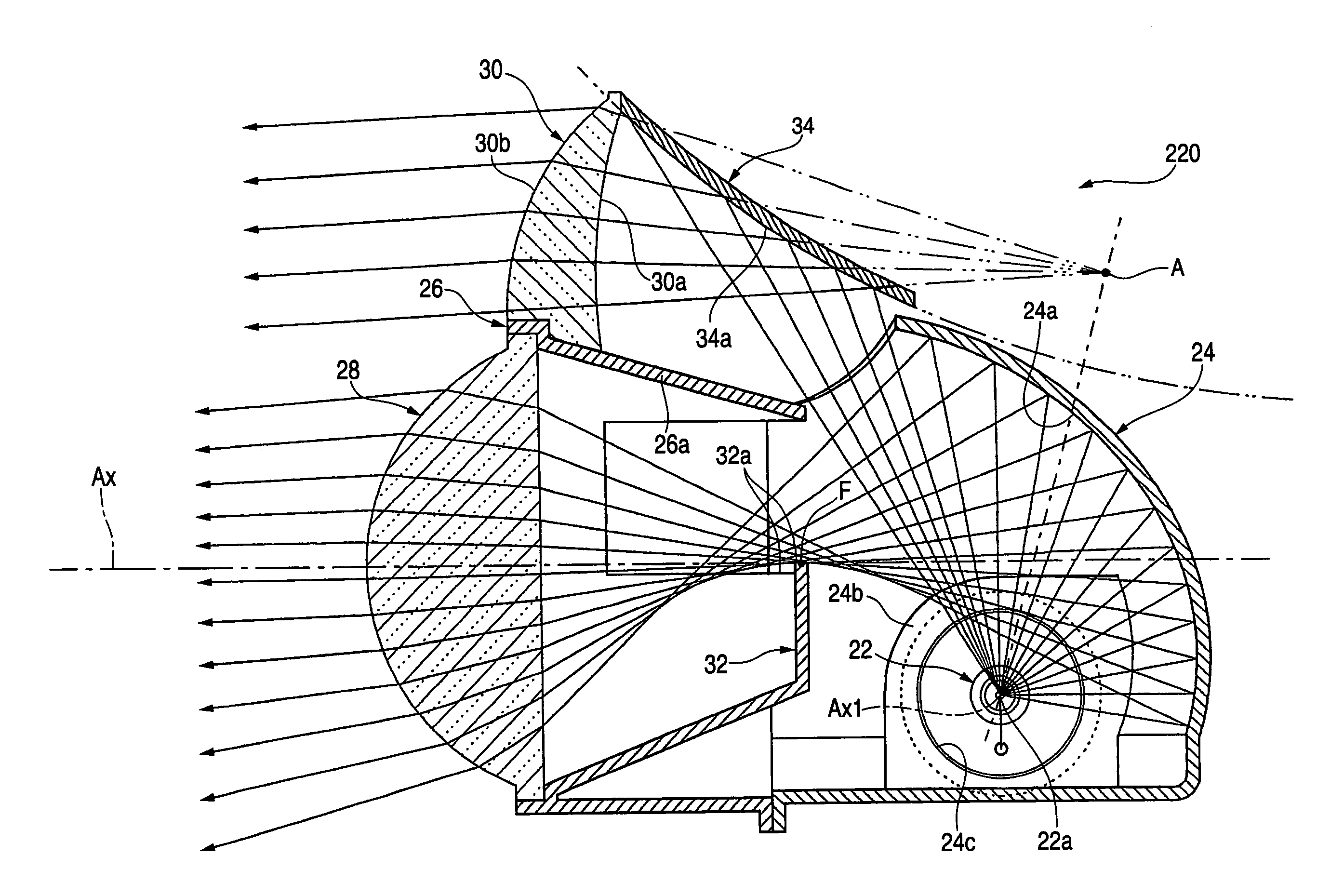
[0101]FIG. 8 is a sectional side view showing, as a single unit, a lighting unit 220 of a vehicle headlamp according to the embodiment.
[0102]As shown in FIG. 8, the basic structure of the lighting unit 220 is entirely the same as that in the second embodiment, and the structure of a light transmitting member 30 is different from that in the second embodiment and is different from that in the second embodiment in that an additional reflector 34 is provided on the rear side of the light transmitting member 30.
[0103]The additional reflector 34 is constituted to reflect a direct light from a light source 22a toward the incidence plane of the light transmitting member 30. In that case, the vertical sectional shape of a reflecting plane 34a of the additional reflector 34 is set to be a hyperbolic shape in which a predetermined point A positioned above an optical axis Ax is a conjugate focal point with the light source 22a. In a vertic...
PUM
 Abstract
Description
Claims
Application Information
 - R&D
- Intellectual Property
- Life Sciences
- Materials
- Tech Scout
- Unparalleled Data Quality
- Higher Quality Content
- 60% Fewer Hallucinations
Browse by: Latest US Patents, China's latest patents, Technical Efficacy Thesaurus, Application Domain, Technology Topic, Popular Technical Reports.
© 2025 PatSnap. All rights reserved.Legal|Privacy policy|Modern Slavery Act Transparency Statement|Sitemap|About US| Contact US: help@patsnap.com


