
Projection optical system unit and projection-type image display apparatus using the same

a projection optical system and projection optical technology, applied in the direction of color television details, instruments, mirrors, etc., can solve the problems of shifting in the inclination and distance of the mirror with respect, difficult to appropriately set and maintain the image formation device and the mirror appropriately, etc., to achieve adequate optical performance, affect the optical performance of the projection optical system, and high reliability

Active Publication Date: 2008-04-22
KONICA MINOLTA OPTO
View PDF9 Cites 15 Cited by
  • Summary
  • Abstract
  • Description
  • Claims
  • Application Information

AI Technical Summary

Benefits of technology

[0005]An object of this invention is to enable appropriate setting and maintenance of an inclination and distance of a mirror with respect to an image formation device in a projection optical system having a reflection optical system, so as to enhance reliability.
[0008]A positional relationship between the image formation device and first curved mirror greatly affects an optical performance of a projection optical system. By fixing the image formation device holder which holds the image formation device and the first mirror holder which holds the first curved mirror to the common pedestal, the inclination and distance of the first curved mirror with respect to the image formation device can be appropriately set and maintained, thereby achieving an adequate optical performance corresponding to an optical design of the projection optical system. In particular, shifts in the inclination and distance of the first curved mirror with respect to the image formation device, arising from shocks and from thermal expansion due to temperature changes, can be prevented or alleviated, so that high reliability is attained.

Problems solved by technology

Consequently it is difficult to maintain the image formation device and the mirrors appropriately in a positional relationship according to an optical design.
Specifically, it is difficult to appropriately set and to maintain inclinations and distances of the mirrors with respect to the image formation device.
In particular, when a shock acts on the apparatus, shifting tends to occur in the inclinations and distances of the mirrors with respect to the image formation device.
Moreover, shifts in the inclinations and distances of the mirrors with respect to the image formation device readily occur due to thermal expansion resulting from temperature changes.
Deteriorated optical performance of the projection optical system due to the shifts in inclinations or distances of the mirrors with respect to the image formation device degrades quality of displayed images.
Thus, the projection-type image display apparatus in which separate support structures support the image formation device and mirrors lacks reliability with respect to shocks and changes in temperature.

Method used


Image

  • Projection optical system unit and projection-type image display apparatus using the same
  • Projection optical system unit and projection-type image display apparatus using the same
  • Projection optical system unit and projection-type image display apparatus using the same

Examples


first embodiment

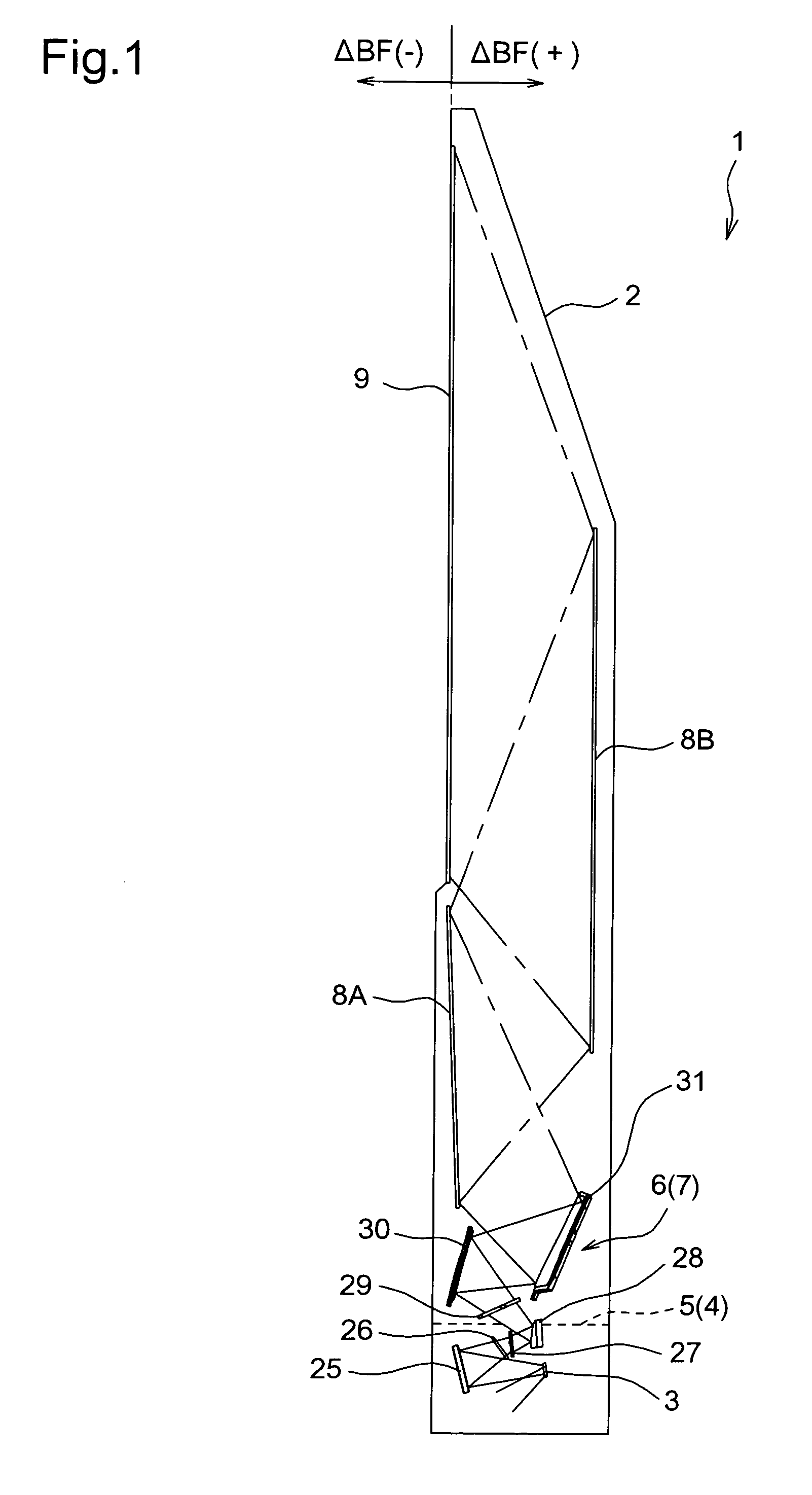
[0034]FIG. 1 shows a rear projection television (rear projection TV) 1 which is an embodiment of a projection-type image display apparatus of the present invention. Accommodated within the casing 2 of the rear projection TV 1 are a digital micromirror device (DMD) 3 which is one example of a reflection-type image formation device, an illumination optical system unit 5 having an illumination optical system 4 which irradiates the DMD 3 with illumination light, and a projection optical system unit 7 having a projection optical system 6 which enlarges and projects projection light reflected by the DMD 3, i.e., image light. Arranged on an upper front of the casing 2 is positioned a screen 9, onto which the image enlarged by the projection optical system 6 is projected through two planar mirrors 8A and 8B.

[0035]Further referring to FIG. 2, in addition to a housing 10 of the illumination optical system unit 5, the casing 2, at a bottom portion, accommodates a lower pedestal component (firs...

second embodiment

[0082]The second embodiment of this invention shown in FIG. 16 differs from the first embodiment with respect to the structures of the lower pedestal component 11, mirror holding component 42 for the concave mirror 25, and mirror holding component 45 for the convex mirror 28.

[0083]The top wall 36a of the second tubular portion 36 extends in the horizontal direction (to the right in FIG. 17) beyond the end wall 36d. Further, the mirror holding component 42 for the concave mirror 25 comprises a protrusion 42c on the upper-left side in FIG. 11, which is the side opposite to the convex mirror 28 facing with the concave mirror 25. The protrusion 42c is fixed to the top wall 36a of the second tubular portion 36. The mirror holding component 45 comprises a protrusion 45a on the upper-right side in FIG. 17, which is the side opposite to the concave mirror 25 facing with the convex mirror 28. The protrusion 45a is fixed to the top wall 36a of the second tubular portion 36. As in the first em...

third embodiment

[0093]The third embodiment of this invention shown in FIG. 18 differs from the first embodiment with respect to the configuration of the heating device 50. The heating device 50 of this embodiment comprises a heating light source 60, which irradiates the side walls 35c of the first tubular portion 35 of the lower pedestal component 11 with light to heat the walls. This heating light source 60 comprises a lamp 61, an elliptical mirror 62 to focus the light emitted by the lamp 61 on the side walls 35c, and a lighting circuit 63 for the lamp 61.

[0094]The controller 54 controls the lighting and extinguishing of the heating light source 60 in order to reduce the temperature difference between the lower pedestal component 11 and the mirror holding component 42, based on the temperature of the lower pedestal component 11 detected by the temperature sensor 52 mounted on the lower pedestal component 11 and on the temperature of the concave mirror 25 detected by the temperature sensor53 mount...


PUM


Abstract

A projection optical system unit has a lower pedestal. The lower pedestal has first and second tubular portions opened to each other. An image formation device holding plate for a DMD is mounted on the first tubular portion at a side where one opening is formed. A mirror holder for a convex mirror is fixed on the second tubular portion at a side where the other opening is formed. A linear heat expansion coefficient in a specific direction of the lower pedestal component is set between 0.8×10⁻⁵ (1 / K) and 3.0×10⁻⁵ (1 / K).

Description

RELATED APPLICATION[0001]This application is based on Japanese Patent Application No. 2005-143827, the contents in which are incorporated herein by reference.BACKGROUND OF THE INVENTION[0002]The present invention relates to a projection optical unit and a projection-type image display apparatus using such the unit. In particular, the present invention relates to a rear projection television, video projector, or other projection-type image display apparatuses having a reflection-type image formation device such as a DMD (Digital Micromirror Device) or the like, or a transmission-type image formation device such as a transmission-type liquid crystal device or the like.[0003]Projection optical systems which enlarge and project images formed by an image formation device in a projection-type image display apparatus can be broadly divided into refraction optical systems, mainly comprising lenses and other refractive optical elements, and reflection optical systems, mainly comprising mirro...

Claims


Application Information

Patent Timeline
Patent Type & Authority Patents(United States)
IPC IPC(8): G03B21/14G03B21/22G03B21/28G03B21/18G03B21/26G03B21/56G02B27/14G02B5/10
CPCG03B21/10G03B21/145G03B21/28H04N9/3141
Inventor ONISHI, SATOSHIMATSUURA, ATSUSHIWATARU, KOHEI
Owner KONICA MINOLTA OPTO
Learn More