
Signal detection by a receiver in a multiple antenna time-dispersive system

a receiver and time-dispersive technology, applied in the field of wireless communication, can solve problems such as inacceptable bit error rate, and achieve the effect of reducing the bit error rate floor caused by time dispersion

Inactive Publication Date: 2008-04-15
LGS INNOVATIONS
View PDF12 Cites 79 Cited by
  • Summary
  • Abstract
  • Description
  • Claims
  • Application Information

AI Technical Summary

Benefits of technology

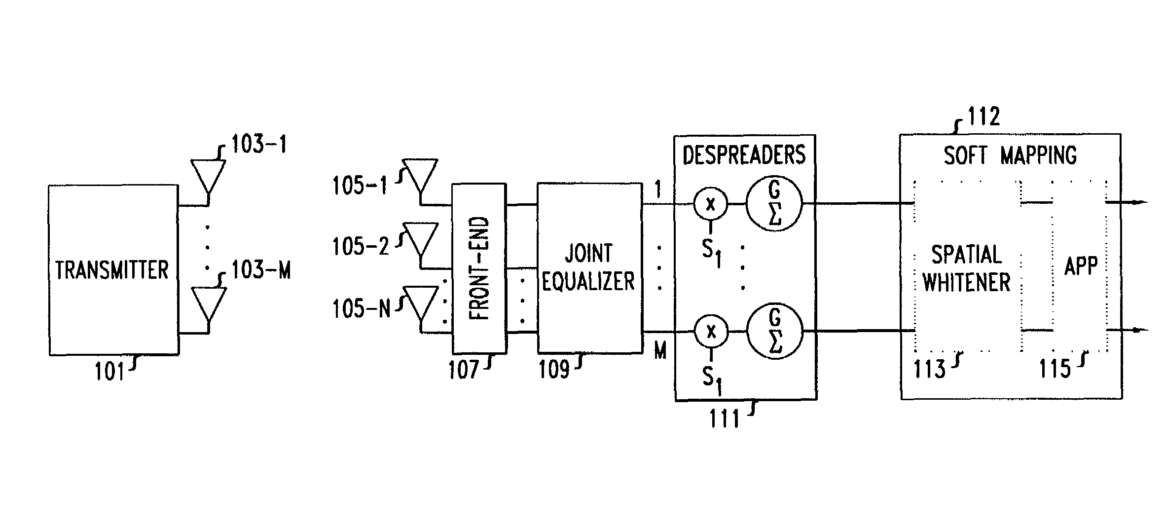
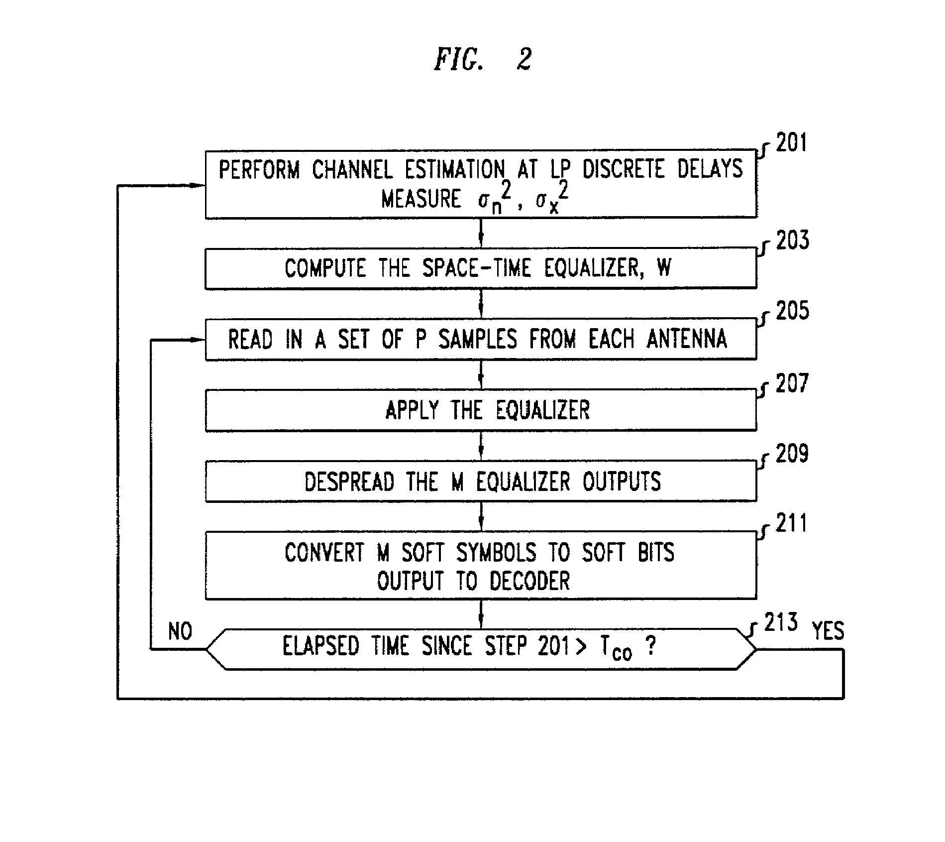
[0004]We have recognized, in accordance with the principles of the invention, that in a MIMO system the bit error rate floor caused by time dispersion can be reduced by employing a joint equalizer for all of the respective transmit antenna—receive antenna pairings that are possible in the MIMO system. Advantageously, the resulting joint equalization compensates not only for the impact of the channel on the transmit antenna—receive antenna pairings but also for the interference of the other transmit antennas on any given receive antenna. In a particular embodiment of the invention, the joint equalizer is a joint minimum mean square error (MMSE) equalizer, and in such an embodiment the joint equalization outperforms simply replicating the prior art minimum mean square error (MMSE) equalizer for each transmit antenna—receive antenna pairing.

Problems solved by technology

Such a non negligible time dispersion causes the various paths to interfere with each other, resulting in a bit error rate floor, i.e., minimum, and so the resulting bit error rate is unacceptable.

Method used


Image

  • Signal detection by a receiver in a multiple antenna time-dispersive system
  • Signal detection by a receiver in a multiple antenna time-dispersive system
  • Signal detection by a receiver in a multiple antenna time-dispersive system

Examples


Embodiment Construction

[0017]The following merely illustrates the principles of the invention. It will thus be appreciated that those skilled in the art will be able to devise various arrangements which, although not explicitly described or shown herein, embody the principles of the invention and are included within its spirit and scope. Furthermore, all examples and conditional language recited herein are principally intended expressly to be only for pedagogical purposes to aid the reader in understanding the principles of the invention and the concepts contributed by the inventor(s) to furthering the art, and are to be construed as being without limitation to such specifically recited examples and conditions. Moreover, all statements herein reciting principles, aspects, and embodiments of the invention, as well as specific examples thereof, are intended to encompass both structural and functional equivalents thereof. Additionally, it is intended that such equivalents include both currently known equival...


PUM


Abstract

In a MIMO system the bit error rate floor caused by time dispersion is reduced by employing a joint minimum mean square error (MMSE) equalizer for all of the respective transmit antenna—receive antenna pairings that are possible in the MIMO system. The resulting joint equalization compensates not only for the impact of the channel on the transmit antenna—receive antenna pairings but also for the interference of the other transmit antennas on any given receive antenna. The joint equalization outperforms simply replicating the prior art minimum mean square error (MMSE) equalizer for each transmit antenna—receive antenna pairings.

Description

TECHNICAL FIELD[0001]This invention relates to the art of wireless communications, and more particularly, to wireless communication systems using multiple antennas at the transmitter and multiple antennas at the receiver, so called multiple-input multiple-output (MIMO) systems.BACKGROUND OF THE INVENTION[0002]It has previously been assumed for MIMO systems that the time dispersion between one or more of the transmit antennas and one or more of the receive antennas was negligible, i.e., the various paths were nonresolvable, as often occurs in low bandwidth systems, because the pulse width is longer than the channel time dispersion. However, it has been recognized that under typical urban (TU) conditions, i.e., the conditions of the so-called “TU” model, that the time dispersion between one or more of the transmit antennas and one or more of the receive antennas is nonnegligible. Such a non negligible time dispersion causes the various paths to interfere with each other, resulting in ...

Claims


Application Information

Patent Timeline
Patent Type & Authority Patents(United States)
IPC IPC(8): H04B1/10H04J99/00H04B1/707H04B7/005H04B7/06H04B7/08H04L1/06H04L25/02H04L25/03
CPCH04B7/0891H04L1/06H04L25/03012H04B1/707H04L25/0242H04L25/03331H04L2025/03605H04L2025/03617
Inventor HUANG, HOWARD CMAILAENDER, LAURENCE EUGENESANDELL, MAGNUSVISWANATHAN, HARISH
Owner LGS INNOVATIONS
Learn More