
Pedestrian protection airbag system

a technology for pedestrians and airbags, applied in the direction of pedestrian/occupant safety arrangements, roofs, tractors, etc., can solve the problems of increasing vehicle body weight, restricting the degree of freedom in the shape of the wiper layout or the cowl top, etc., and achieve the effect of minimizing the influence of the shape or structure of the cowl top

Inactive Publication Date: 2008-04-15
HONDA MOTOR CO LTD
View PDF9 Cites 28 Cited by
  • Summary
  • Abstract
  • Description
  • Claims
  • Application Information

AI Technical Summary

Benefits of technology

The present invention is about a pedestrian protection airbag system that can be mounted on a vehicle without affecting the vehicle's appearance or air intake. The system includes an airbag module that is supported by the vehicle's damper housings and an inflator that generates gas to deploy the airbag. The airbag module has a cover that can be opened smoothly during deployment. The invention also includes a reinforcing member that connects the damper housings and functions as a retainer for the inflator and airbag. The cover of the airbag module is divided into multiple lids to improve its appearance. The technical effects of the invention are improved safety for pedestrians and improved aesthetics for the vehicle.

Problems solved by technology

However, in this conventional arrangement, since the airbag module is disposed within the cowl top, the airbag module disadvantageously impedes air being taken into a vehicle compartment through the cowl top and restricts the degree of freedom in a wiper layout or a cowl top shape.
Further, since the airbag module receives a downward reaction load when the airbag is deployed, it is necessary to enhance the rigidity of the cowl top which supports the airbag module and the rigidity of a dashboard which is connected to the cowl top, disadvantageously leading to an increase in the vehicle body weight.

Method used


Image

  • Pedestrian protection airbag system
  • Pedestrian protection airbag system
  • Pedestrian protection airbag system

Examples


first embodiment

[0032]The operation of the present invention having the above-mentioned arrangement is now described.

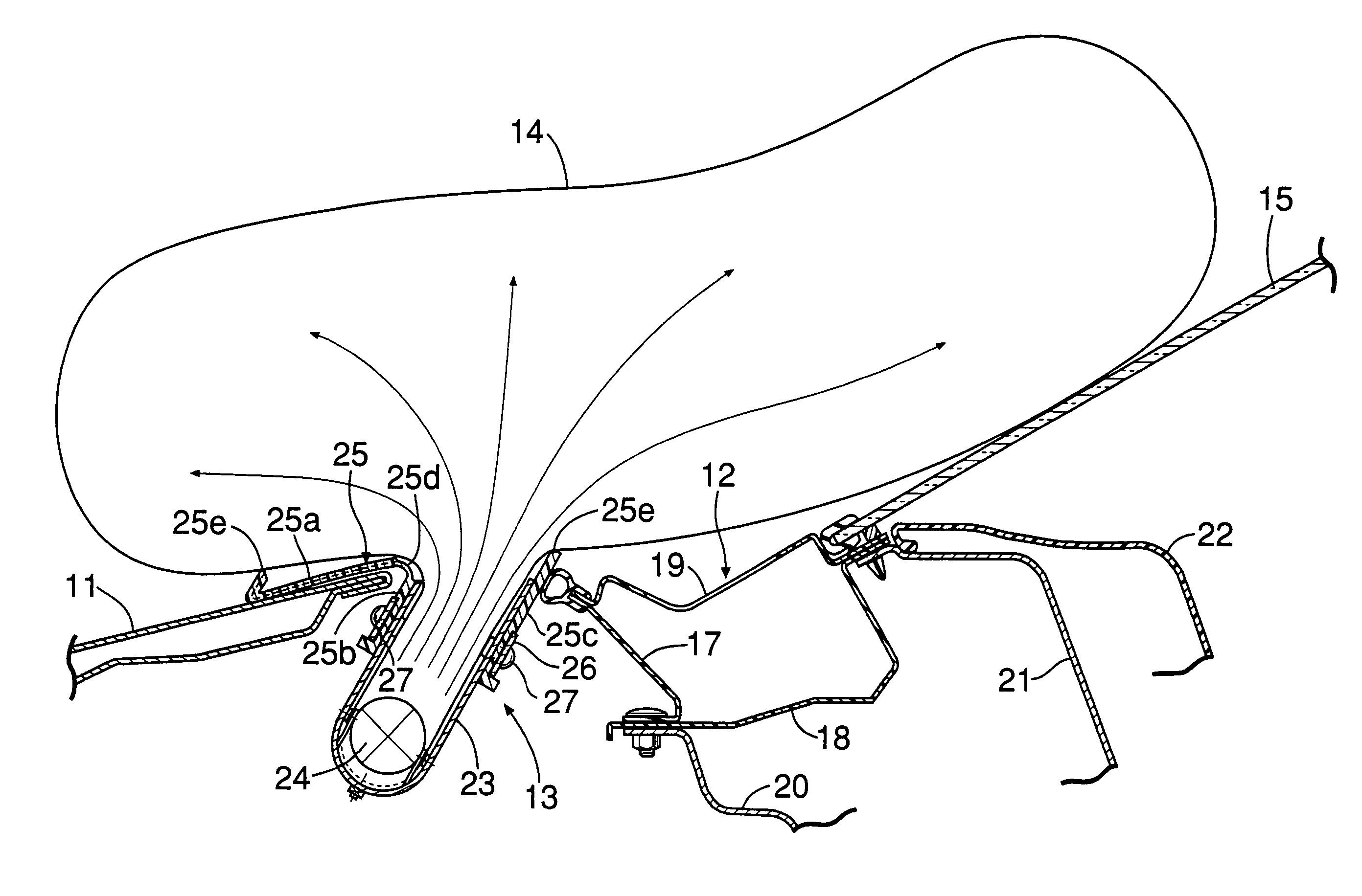
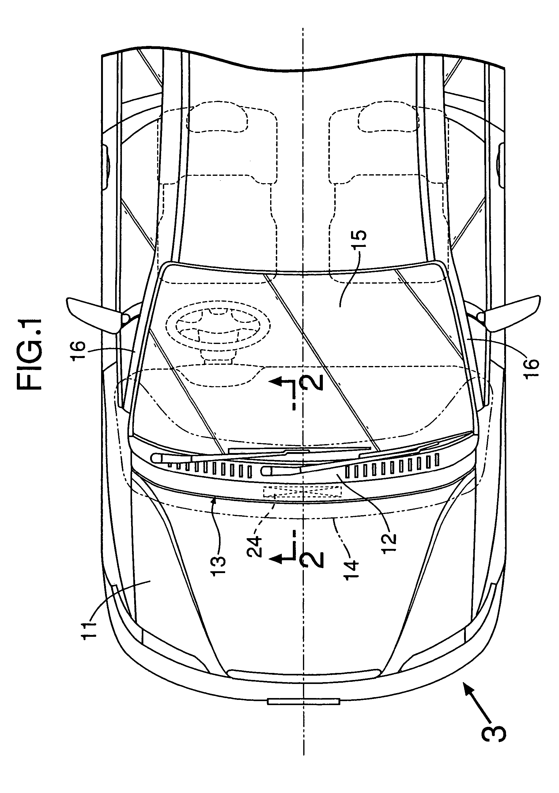
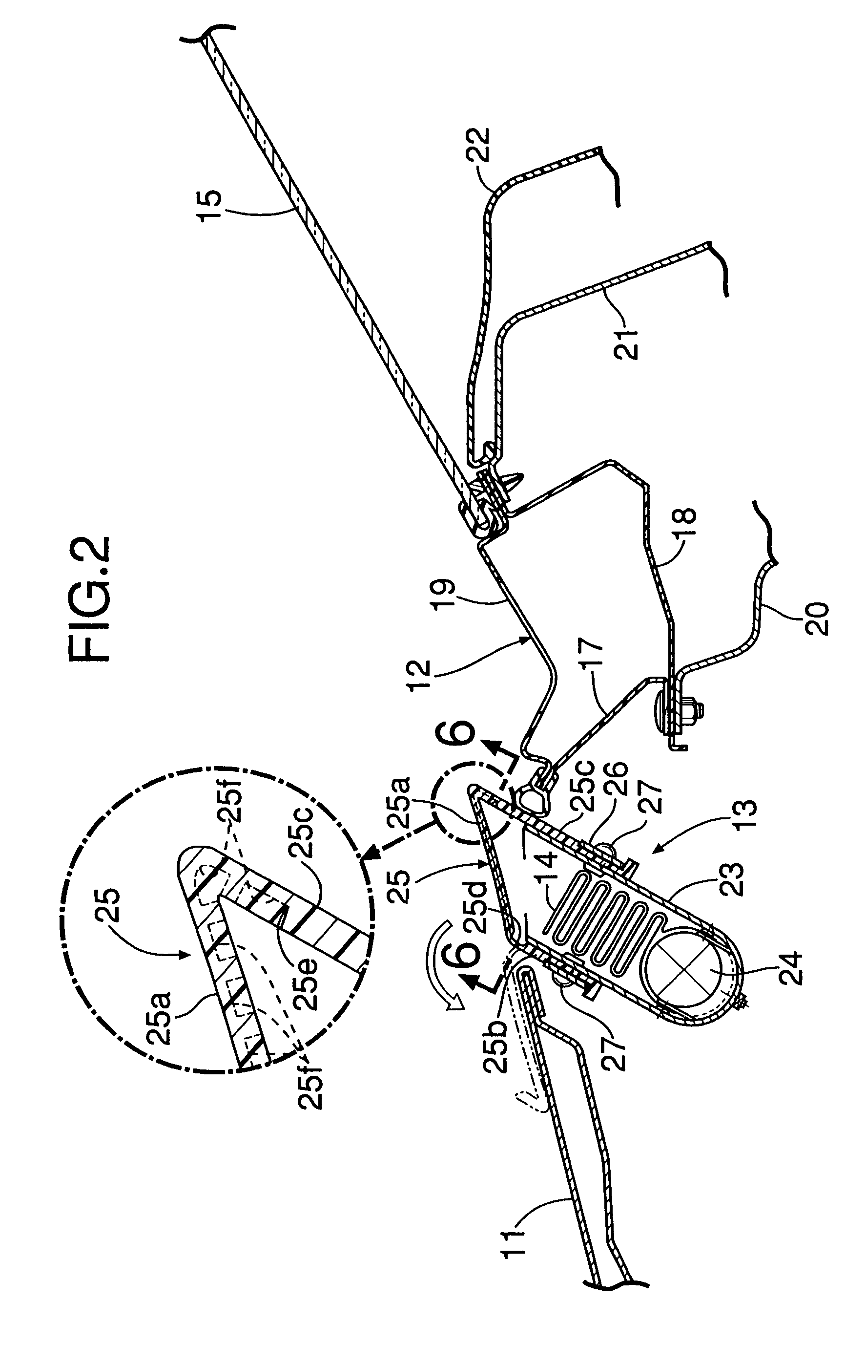
[0033]When the impact of a pedestrian being hit by the vehicle is detected, the inflator 24 generates gas to inflate the folded airbag 14, and the resultant pressure acts on the reverse face of the upper wall 25a of the cover 25. Since the comb-shaped brittle portions 25e and 25f are formed in the synthetic resin cover 25, the brittle portions 25e and 25f are ruptured by the pressure of the airbag 14, so that the plurality of lids 28 which are divided into strips open forward with the hinge part 25d at the front end serving as a fulcrum, thereby deploying the airbag 14 through the resultant opening. As shown in FIG. 1 and FIG. 7, the deployed airbag 14 covers the upper face of the cowl top 12, the front face of the windshield 15, and the front faces of the front pillars 16, thereby protecting the pedestrian who has been bounced up onto the hood 11.

[0034]Since the airbag module 13 is ...

second embodiment

[0036]the present invention is now described by reference to FIG. 8 and FIG. 9.

[0037]In the above-described first embodiment, the hinge part 25d is formed integrally with the synthetic resin cover 25, providing a possibility that the hinge part 25d might become brittle to split at low temperature. In the second embodiment, a cover 25 includes an iron hinge member 41 in place of a front wall 25b and a hinge part 25d. The hinge member 41 includes: a front wall 41a secured by rivets 27 to a retainer 23; and upper wall strips 41b which are formed by splitting an upper wall and secured by hot upsetting to lower faces of a plurality of lids 28.

[0038]In accordance with the second embodiment, since the iron hinge member 41 functions as a fulcrum when the upper wall 25a of the cover 25 opens while splitting into the plurality of lids 28, the hinge member 41 does not break to fly asunder even at low temperature. The other components and operational effects of the second embodiment are the sam...

third embodiment

[0039]the present invention is now described by reference to FIG. 10.

[0040]In the cover 25 of the second embodiment, the upper wall 25a and the rear wall 25c are integral components; however, in a cover 25 of the third embodiment, a rear wall 25c is formed from a member that is separate from an upper wall 25a, and is secured to the upper wall 25a by hot upsetting.

[0041]In accordance with the third embodiment, forming the upper wall 25a and the rear wall 25c as separate members enables the cover 25 to be easily molded. The other components and operational effects of the third embodiment are the same as those of the second embodiment.


PUM


Abstract

In a pedestrian protection airbag system, an airbag module extending in the lateral direction of a vehicle body is disposed between a rear edge of a hood and a front edge of a cowl top, thereby mounting the airbag module without affecting the intake of air into a vehicle compartment or the positioning of wipers; and the left and right ends of the airbag module are supported by upper parts of left and right front wheel damper housings, whereby the damper housings obtain a high rigidity to reliably bear a reaction force during deployment of an airbag without particularly enhancing the rigidity of the cowl top. Thus, it is possible to rigidly support the airbag module in the pedestrian protection airbag system while minimizing the influence on the shape or structure of the cowl top.

Description

RELATED APPLICATION DATA[0001]The Japanese priority application No. 2004-246187 upon which the present application is based is hereby incorporated in its entirety herein by reference.BACKGROUND OF THE INVENTION[0002]1. Field of the Invention[0003]The present invention relates to a pedestrian protection airbag system comprising an airbag and an inflator that generates gas to deploy the airbag along an upper face of a cowl top and a front face of a windshield upon contact with a pedestrian.[0004]2. Description of the Related Art[0005]Japanese Patent Application Laid-open No. 2003-252140 discloses a pedestrian protection airbag system comprising an airbag module which is disposed within a cowl top positioned between a rear edge of a hood and a front edge of a windshield of an automobile; and when the automobile hits a pedestrian, the airbag is deployed from the cowl top so as to protect the pedestrian.[0006]However, in this conventional arrangement, since the airbag module is disposed ...

Claims


Application Information

Patent Timeline
Patent Type & Authority Patents(United States)
IPC IPC(8): B60R21/34B60R21/2165B60R21/36
CPCB60R21/36B60R21/2165B60R21/2171
Inventor SASAKI, SAKAENAKANE, KENOKAMOTO, YUTAKAKIKUCHI
Owner HONDA MOTOR CO LTD
Learn More