
Optical probe for optical imaging system

a technology of optical imaging and optical probes, applied in the field of optical probes, can solve the problems of effective loosening of manufacturing tolerances and lack of symmetry, and achieve the effect of loosening manufacturing tolerances

Active Publication Date: 2008-04-08
VIOPTIX
View PDF9 Cites 85 Cited by
  • Summary
  • Abstract
  • Description
  • Claims
  • Application Information

AI Technical Summary

Benefits of technology

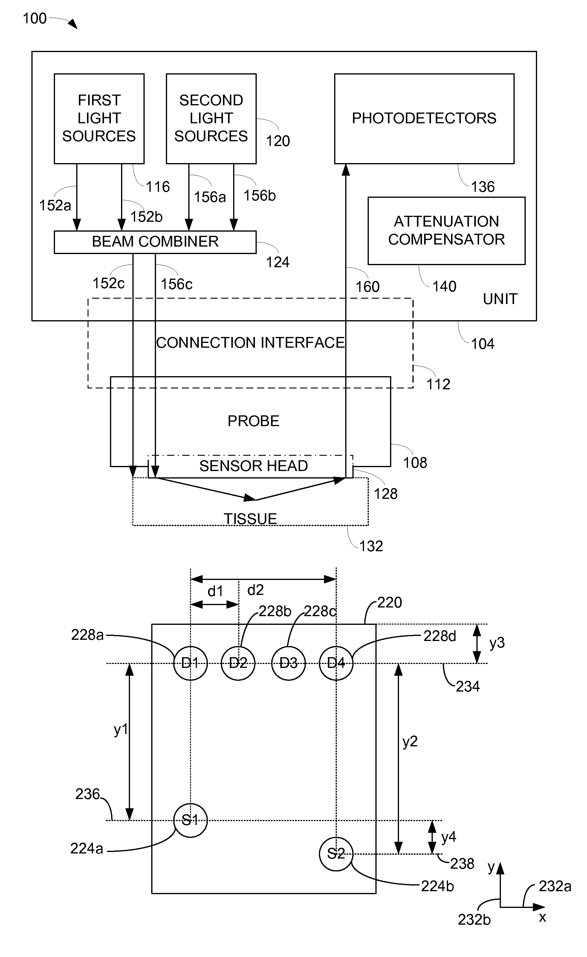
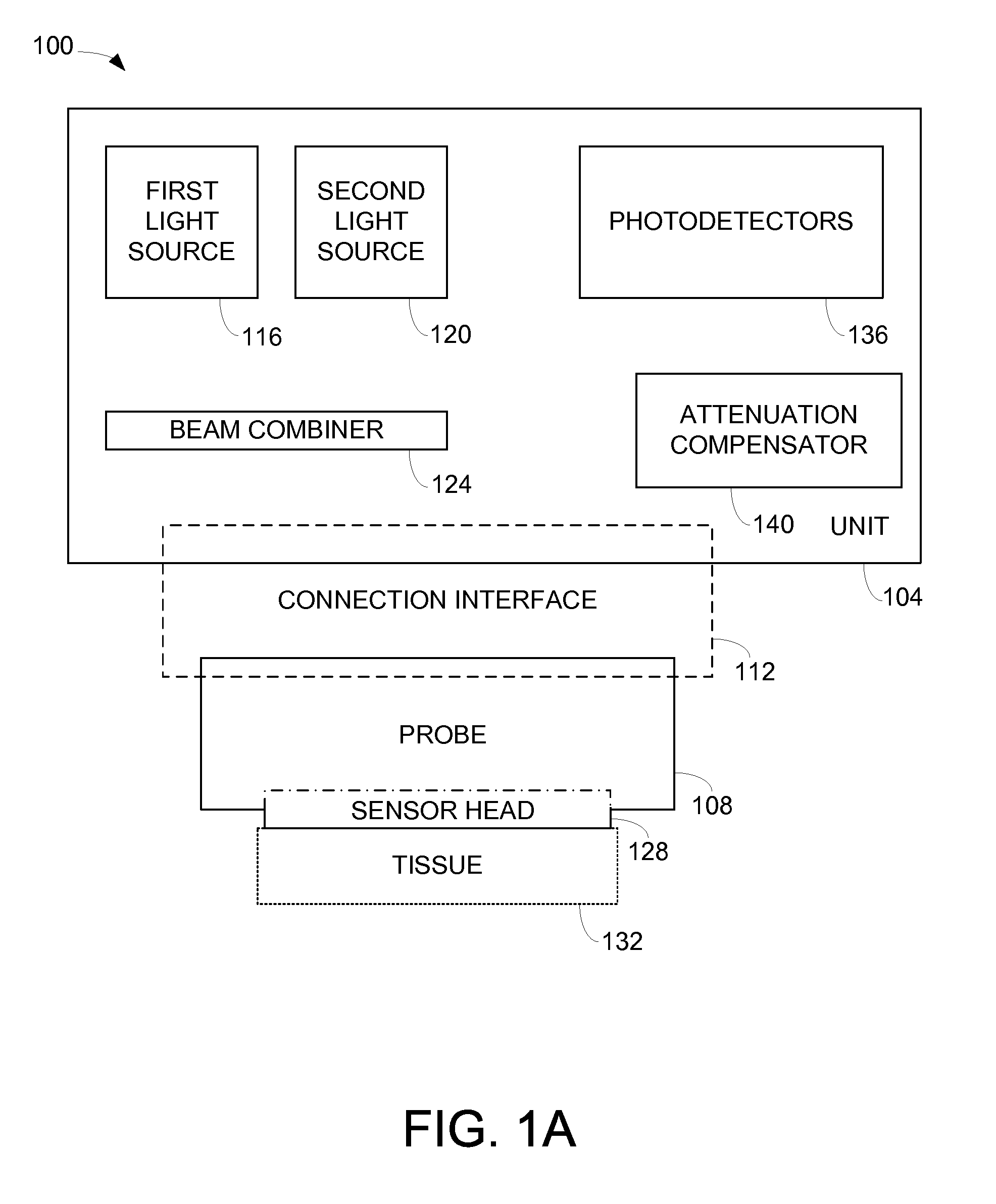
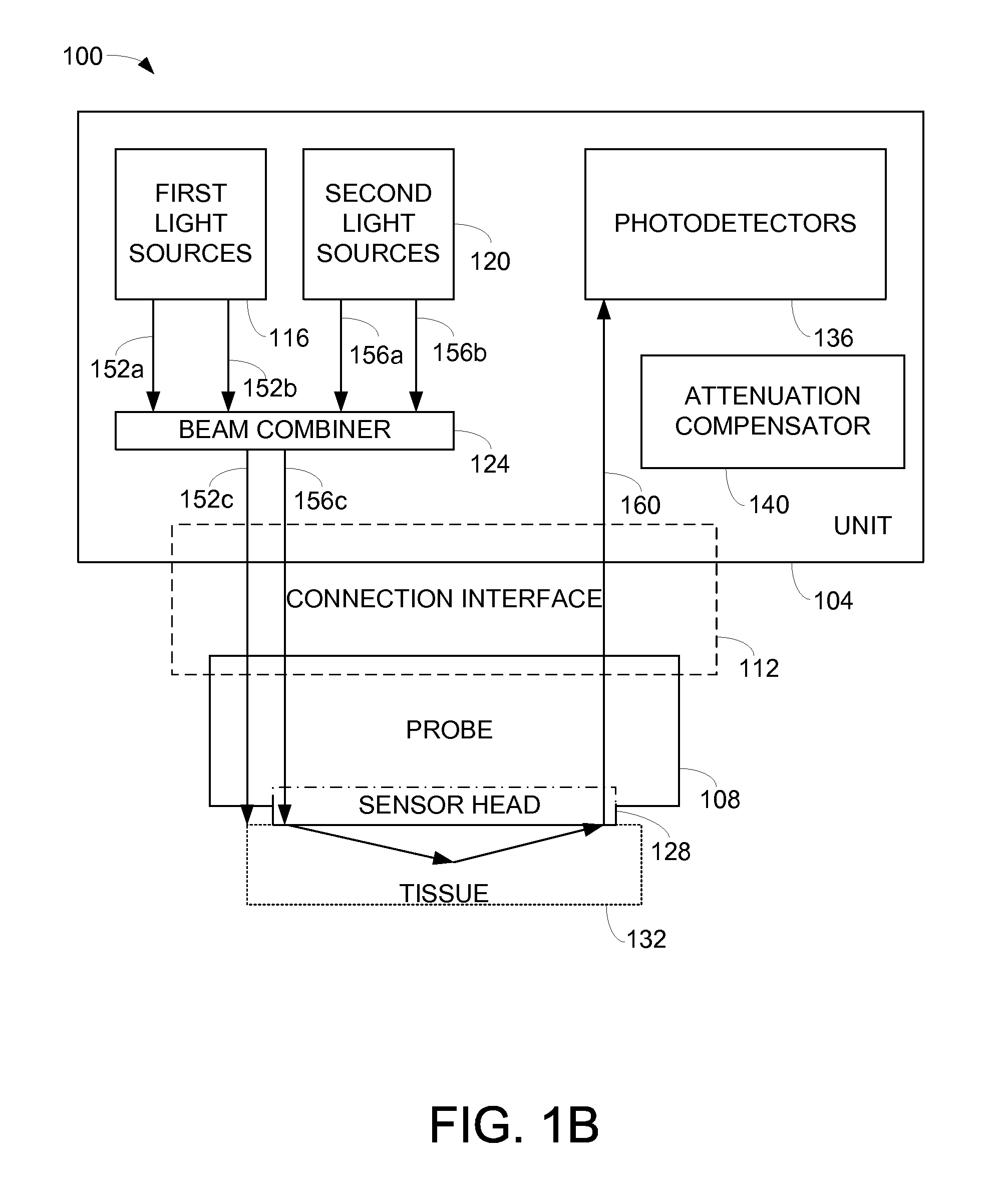
The present invention relates to a probe with a sensor that supports source fibers and detector fibers in a non-symmetrical arrangement. This allows the sensor to monitor tissue with an underlying anatomy that is not symmetrical. The non-symmetrical arrangement compensates for any attenuation associated with the positioning of the optical fibers with respect to the sensor through the use of software code devices executing with respect to an optical imaging system. The invention also includes a method for taking an oxygen saturation measurement of tissue using an optical system that utilizes a probe with a sensor head in which a first source structure, a second source structure, and a detector arrangement are not symmetrically arranged. The technical effects of the invention include improved monitoring of tissue with an underlying anatomy that is not symmetrical and compensation for attenuation associated with the positioning of optical fibers with respect to the sensor.

Problems solved by technology

The lack of symmetry also effectively loosens manufacturing tolerances associated with the manufacture of such sensor.

Method used


Image

  • Optical probe for optical imaging system
  • Optical probe for optical imaging system
  • Optical probe for optical imaging system

Examples


Embodiment Construction

[0028]A sensor head which is such that optical fibers that are coupled to light sources are arranged in an offset orientation relative to optical fibers that are coupled to detectors allows the sensor head to be utilized in areas in which tissue being monitored is not substantially symmetric. Any attenuation associated with the offset orientation of optical fibers that are coupled to light sources is typically compensated for through software. Such a sensor head is relatively easy to manufacture in that the placement of optical fibers that are coupled to light sources is less rigid, i.e., any slight variation in the placement of the optical fibers may be corrected for using the software that compensates for attenuation. In addition, the use of software to compensate for attenuation associated with the placement of optical fibers on a sensor head essentially enables the sensor head to be used with both symmetric and asymmetric tissue anatomies.

[0029]As will be understood by those ski...


PUM

PropertyMeasurementUnit
lengthaaaaaaaaaa
diameteraaaaaaaaaa
lengthaaaaaaaaaa

Abstract

Methods and apparatus for monitoring oxygen saturation levels in tissue are disclosed. According to one aspect of the present invention, a sensor arrangement for use in an optical imaging system includes a first source structure, a second source structure, and a detector arrangement. The first source structure provides a first beam of light and the second source structure provides a second beam of light. The detector arrangement includes detector structures that have centerpoints, and receives the first and second beams of light after the first and second beams of light are reflected off of an external surface. The detector arrangement is arranged to define a first axis that passes through the centerpoint of each detector structure, and a distance from a centerpoint of the first source structure to the first axis is not equal to a distance from a centerpoint of the second source structure to the first axis.

Description

BACKGROUND OF THE INVENTION[0001]1. Field of Invention[0002]The present invention relates generally to optical imaging systems that monitor oxygen levels in tissue. More specifically, the present invention relates to optical probes that include sources and detectors that are not symmetrically arranged on sensor heads of the optical probes.[0003]2. Description of the Related Art[0004]Near-infrared spectroscopy has been used for non-invasive measurement of various physiological properties in animal and human subjects. The basic principle underlying the near-infrared spectroscopy is that physiological tissues include various highly-scattering chromophores to the near-infrared waves with relatively low absorption. Many substances in a medium may interact or interfere with the near-infrared light waves propagating therethrough. Human tissues, for example, include numerous chromophores such as oxygenated hemoglobin, deoxygenated hemoglobin, water, lipid, and cytochrome, where the hemoglob...

Claims


Application Information

Patent Timeline
Patent Type & Authority Patents(United States)
IPC IPC(8): G01J1/42A61B5/00G01N21/47
CPCG01N21/3151A61B5/14552
Inventor LASH, ROBERT E.MAO, JIAN-MINLIN, QIONG
Owner VIOPTIX
Learn More