
Joint system

a joint system and system technology, applied in the field of joint systems, can solve the problems of being difficult to remove or be unable to be pivoted into a stowed position, affecting the service life of the wakeboard, and the wakeboard tower once installed,

Inactive Publication Date: 2010-12-21
N A TAYLOR CO INC
View PDF22 Cites 3 Cited by
  • Summary
  • Abstract
  • Description
  • Claims
  • Application Information

AI Technical Summary

Benefits of technology

"The patent text describes a hinge system that connects a wakeboard tower or other frame to a boat, such as a windshield frame. The system uses a mounting ball and a connector that can move in a folding plane. The connector can accommodate misalignment and can also allow for the passage of wires or hoses. The system provides a clearance amount to allow for angular and rotational misalignment. The technical effect of this hinge system is that it reduces manufacturing costs and tolerances while still allowing for secure and easy connection between the frame and the accessory."

Problems solved by technology

There are, however, a number of problems with existing wakeboard tower systems.
In some arrangements, the wakeboard towers, once installed, are difficult to remove or are unable to be pivoted into a stowed position.
In this context, however, at the hinge points, the wires are typically exposed and are subject to wear through catching or the like or exposure to the harsh marine environment.

Method used


Image

  • Joint system
  • Joint system
  • Joint system

Examples


Embodiment Construction

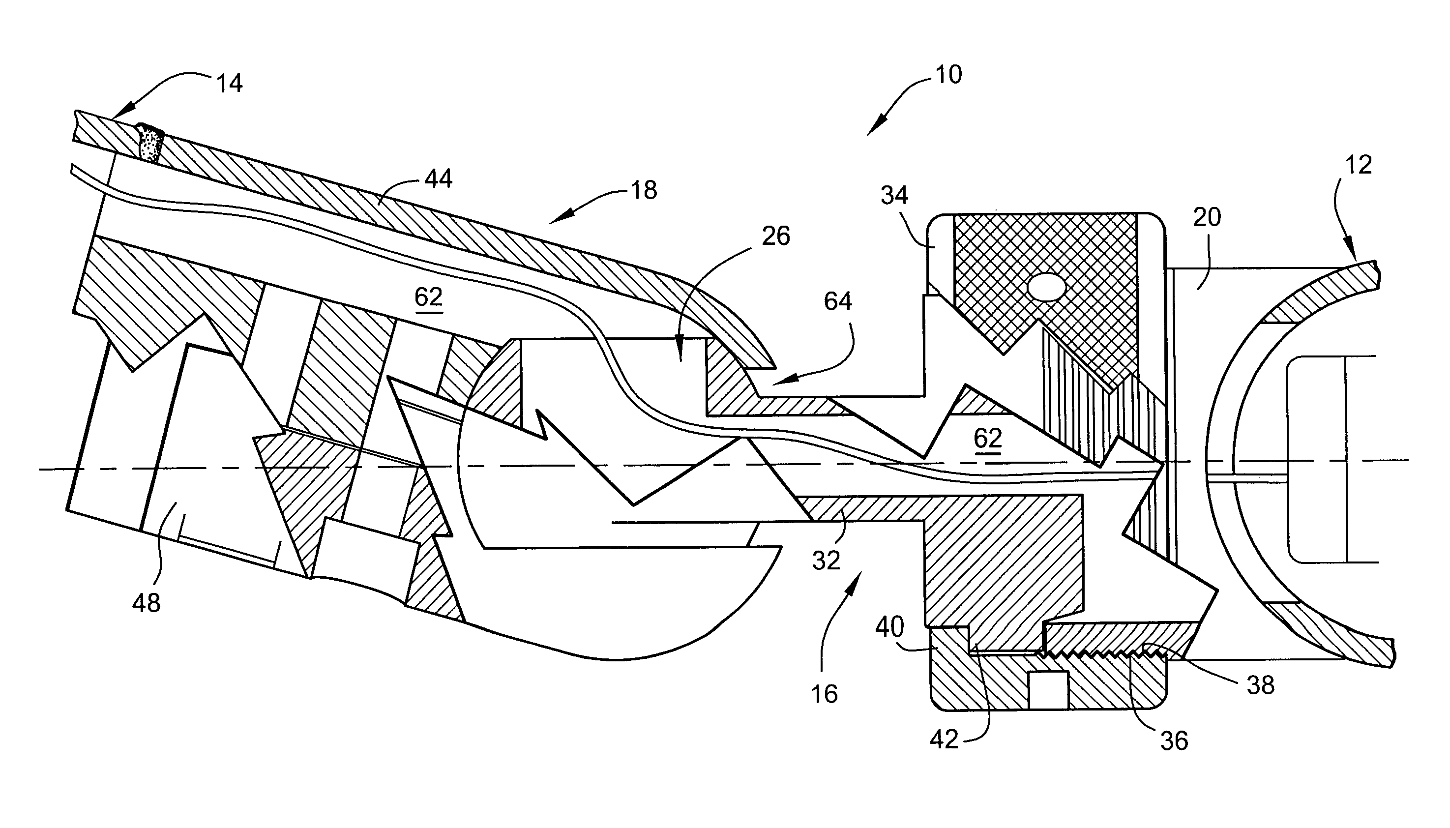
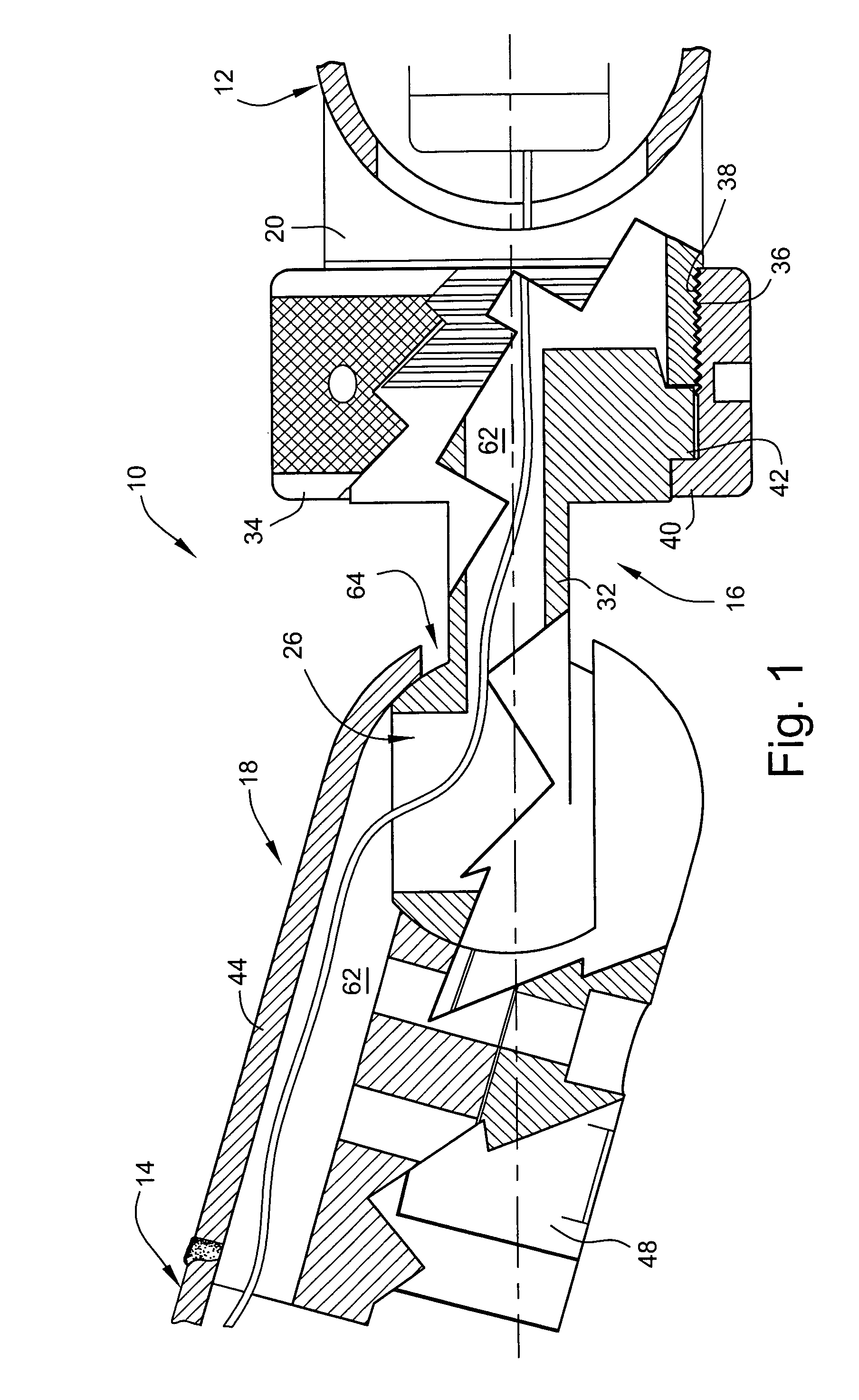
[0018]FIG. 1 is a cross sectional view of the joint system 10 according to the present invention. As shown, the joint system 10 provides a pivotable connection between two frame members, which need not necessarily be similarly oriented. In the exemplary embodiment illustrated in FIG. 1, the joint system 10 is connected between a portion of a windshield frame 12 and a tower leg 14 of a wakeboard tower. The joint system is affixed between the frame members (e.g., windshield frame 12 and tower leg 14) via any suitable means such as welding. As noted, the embodiment illustrated in FIG. 1 is exemplary, and the joint system 10 can provide a pivotable connection between any two members.

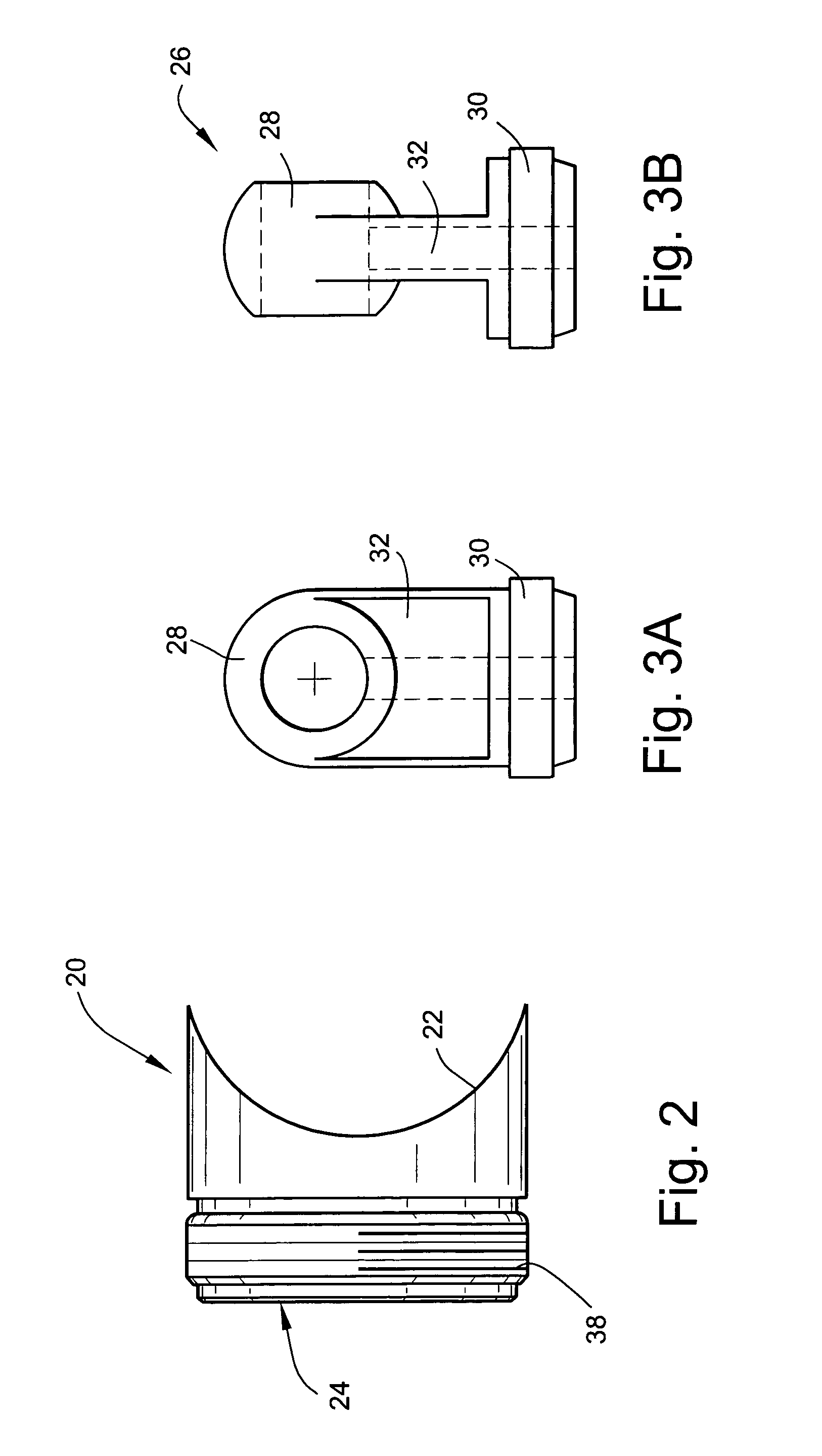
[0019]The joint system 10 includes a mounting ball assembly 16, which is affixable to the first frame member 12. A connector 18 is engageable with the mounting ball assembly 16 at one end and is affixable to the second frame 14 at an opposite end.

[0020]With continued reference to FIG. 1 and with reference to...


PUM


Abstract

A joint system enables pivotable coupling between a first frame member and a second frame member. The joint system includes a mounting ball assembly affixable to the first frame member, and a connector engageable with the mounting ball assembly at one end and affixable to the second frame at an opposite end. The connector is constructed such that it is movable on the mounting ball assembly in a folding plane and through a clearance amount in a clearance plane substantially perpendicular to the folding plane. A continuous passage is defined through the mounting ball assembly and the connector.

Description

CROSS-REFERENCES TO RELATED APPLICATIONS[0001](NOT APPLICABLE)STATEMENT REGARDING FEDERALLY SPONSORED RESEARCH OR DEVELOPMENT[0002](NOT APPLICABLE)BACKGROUND OF THE INVENTION[0003]The present invention relates to a joint system pivotally connecting a first frame member to a second frame member and, more particularly, to a joint system including a mounting ball assembly and connector constructed to enable free movement in a folding plane with a clearance amount in a clearance plane generally perpendicular to the folding plane.[0004]A wakeboard tower is a boat accessory typically extending above and across the passenger cabin over the windshield. The tower is designed to support a tow rope for a wakeboard rider. Typically, the wakeboard tower is comprised of tubular frame elements formed of a sturdy material such as aluminum securely fixed at four points to the boat hull. See, for example, U.S. Pat. Nos. D465,194 and 5,979,350, the contents of which are hereby incorporated by referenc...

Claims


Application Information

Patent Timeline
Patent Type & Authority Patents(United States)
IPC IPC(8): F16D3/00
CPCB63B19/02Y10T403/32631
Inventor ERSKINE, EDWARD J.
Owner N A TAYLOR CO INC
Learn More