
Method and apparatus for improving efficiency of constraint solving

a technology of constraint solving and efficiency, applied in the field of solving sets of constraints, can solve problems such as complex assignment of variables to their variables, and achieve the effect of increasing efficiency (or computing speed, less time)

Active Publication Date: 2008-04-01
SYNOPSYS INC
View PDF2 Cites 3 Cited by
  • Summary
  • Abstract
  • Description
  • Claims
  • Application Information

AI Technical Summary

Benefits of technology

This approach significantly reduces the time required to find solutions to constraint sets by skipping unnecessary processing steps and improving the overall efficiency of constraint solving, enabling faster verification of digital electronic circuits.

Problems solved by technology

While constraints provide a powerful specification language, for such applications as design verification, finding an assignment to their variables that satisfies them can be complex.

Method used


Image

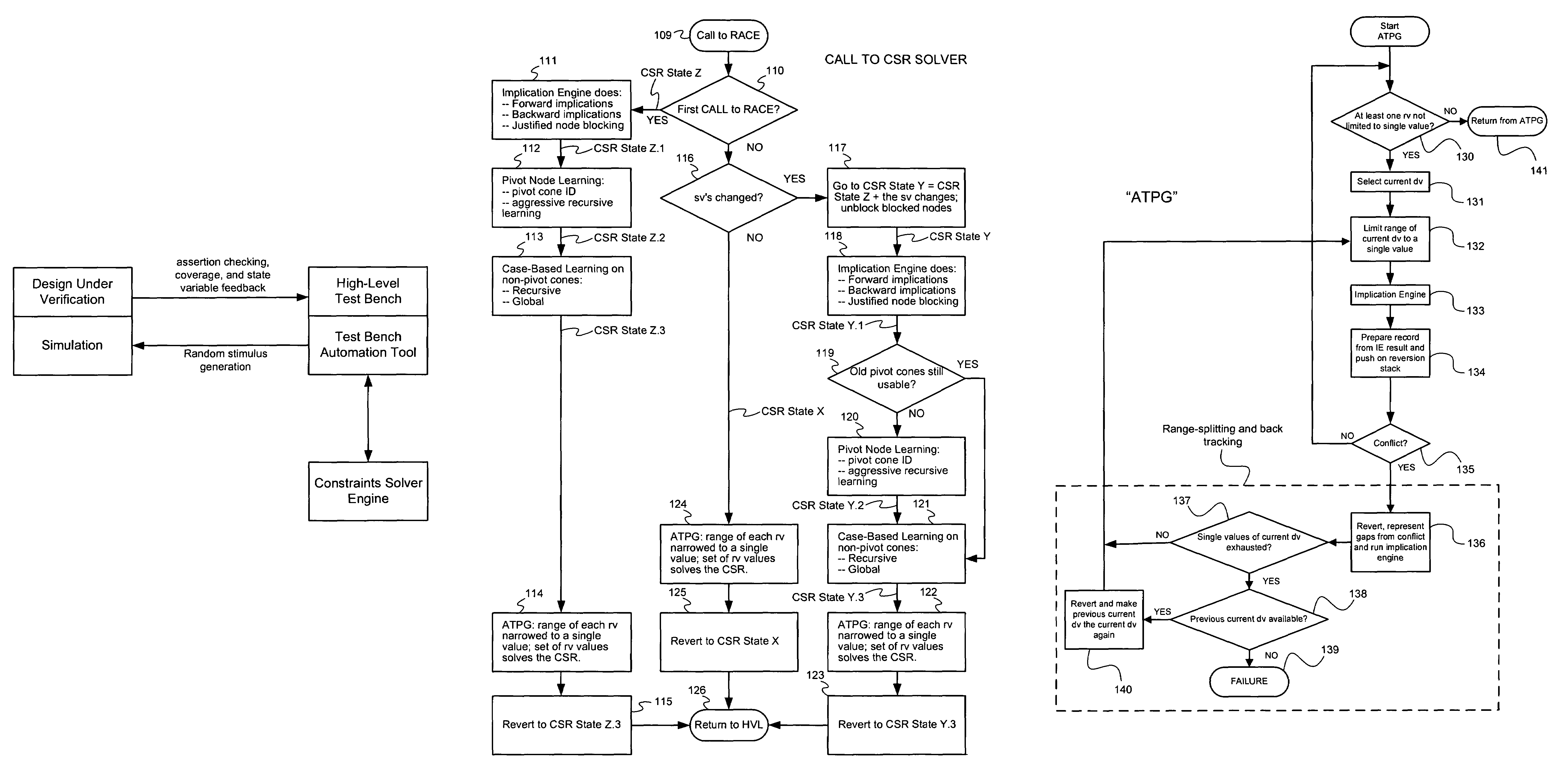
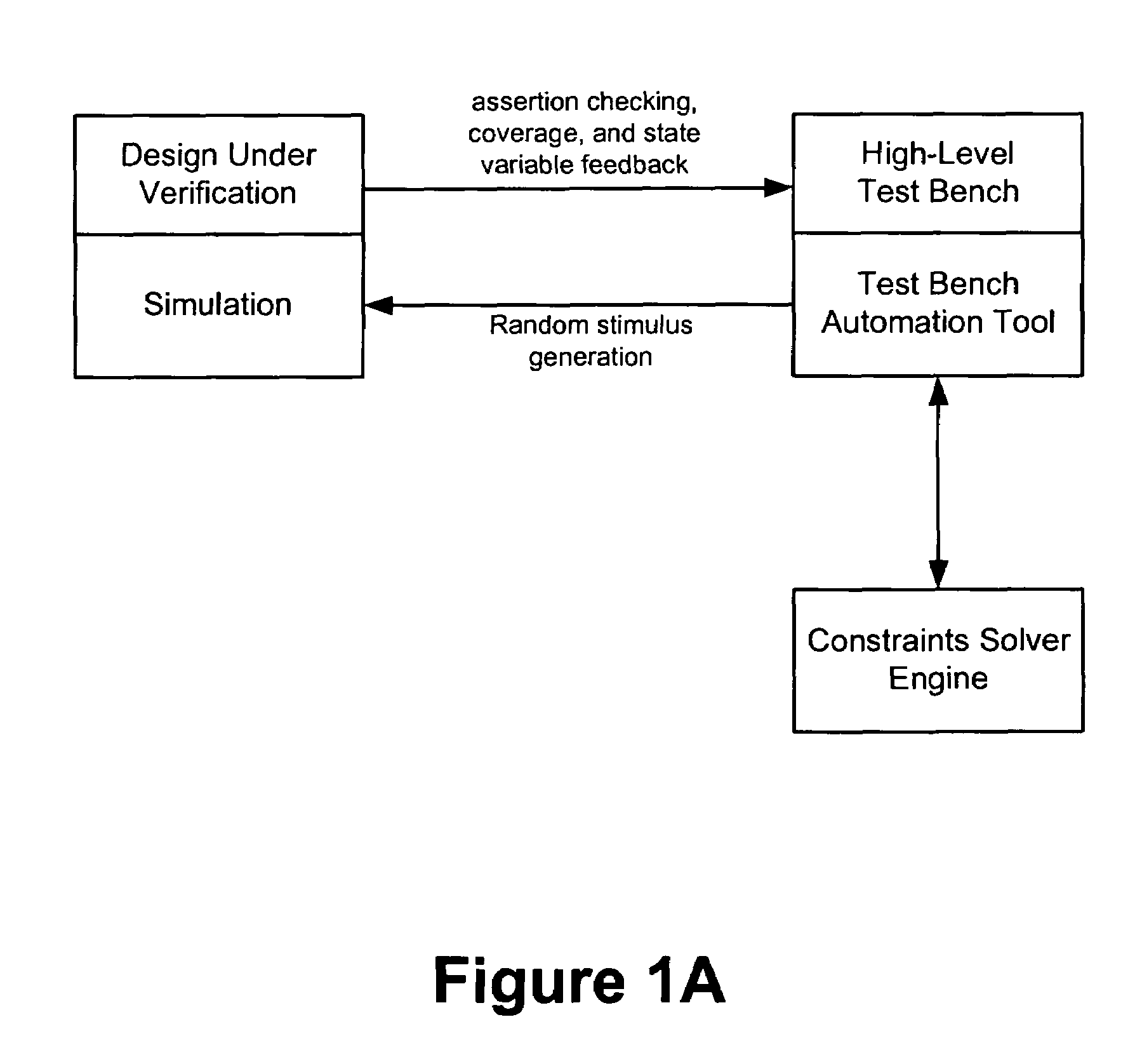
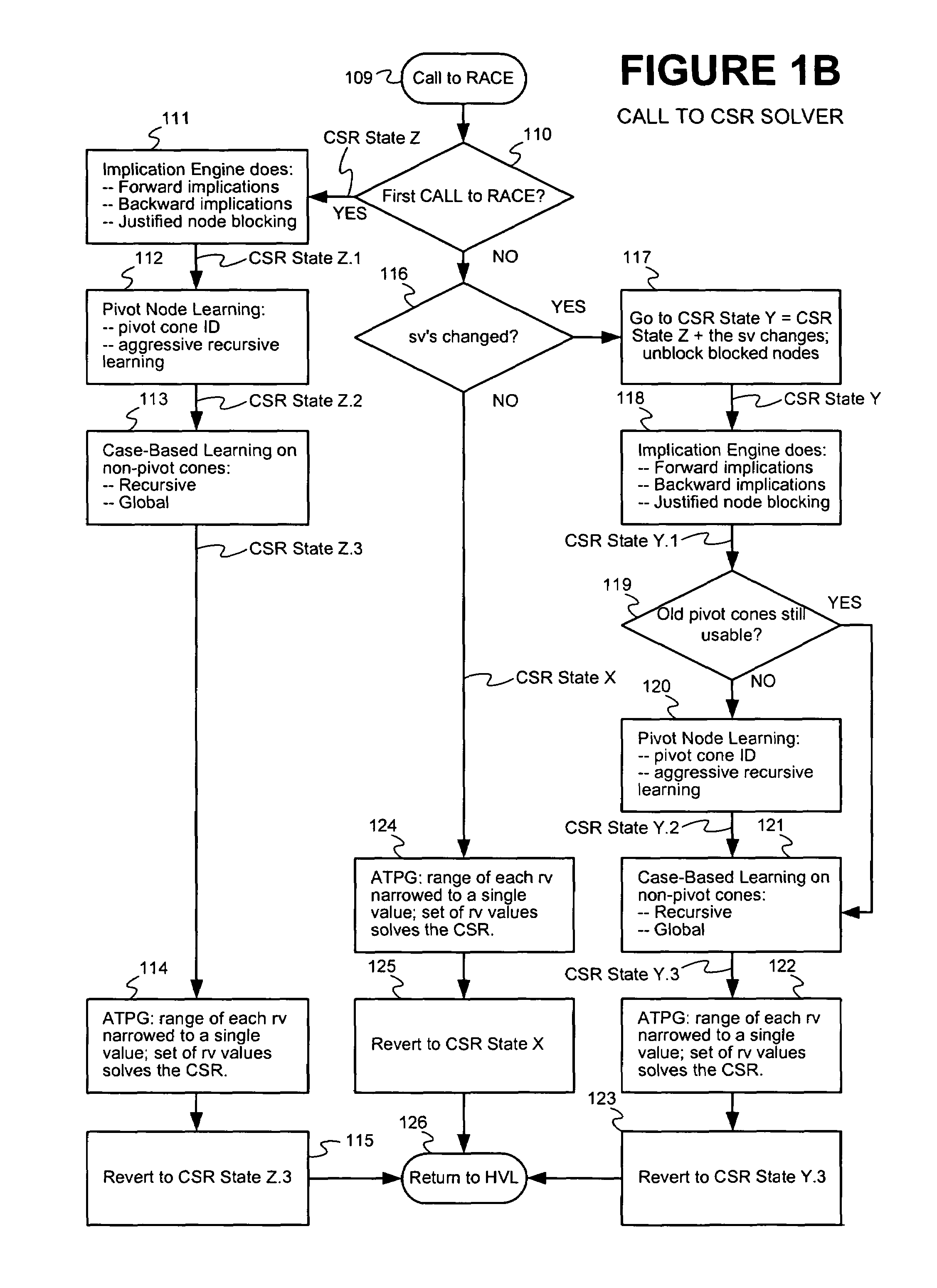
  • Method and apparatus for improving efficiency of constraint solving
  • Method and apparatus for improving efficiency of constraint solving
  • Method and apparatus for improving efficiency of constraint solving

Examples


example 1

[0333]Consider the following constraint solving problem, labeled Example 1, that is written in the Vera HVL:[0334]Example 1

[0335]

rand bit[3:0] a, b;rand integer c;constraint c1 {a + b == c * 2;}constraint c2 {c > 0;}

[0336]Here “a” and “b” are 4-bit unsigned random variables and “c” is a 32-bit signed random variable. Thus, “a,”“b,” and “c” can possibly take, respectively, 16, 16 and 232 values (the integer data type is assumed to be comprised of a 32 bit word). In the OpenVera language, c1 and c2 represent constraint blocks, with each block containing a constraint expression (or constraint). As can be seen, the constraint expression of block c1 is a declarative statement regarding a relationship that must be maintained over the variables “a,”“b,”“c,” and the constant value of 2. The constraint expression of block c2 is a declarative statement regarding a relationship that must be maintained between the variable “c” and the constant value of zero. The constraint solving problem compr...


PUM


Abstract

Techniques are presented for identifying blockable subsets. Blockable subsets can increase the efficiency by which solutions to a constraint set representation (CSR) can be found. Nodes of a blockable subset can be marked as “blocked” and learning or implication procedures, used as part of a CSR solving process, can be designed to skip nodes marked as blocked. The identification of a particular blockable subset is typically associated with certain conditions being true. If and when the conditions no longer hold, the nodes of the blockable subset need to be unblocked. One type of blockable subset can be identified during the operation of an implication engine (IE) by a technique called justified node blocking (JNB). Another type of blockable subset can be identified by a technique called pivot node learning (PNL). PNL can be applied in-between application of an IE and application of case-based learning.

Description

CROSS REFERENCE TO RELATED APPLICATIONS[0001]This application is related to the following four U.S. patent applications, all of which are herein incorporated by reference in their entirety:[0002]“Method and Apparatus For Improving Efficiency of Constraint Solving,” filed on May 2, 2005, having inventor Mahesh A. Iyer, U.S. patent application Ser. No. 11 / 120,920.[0003]“Method and Apparatus For Solving Constraints,” filed on Aug. 16, 2003, having inventor Mahesh A. Iyer, U.S. patent Office application Ser. No. 10 / 641,845.[0004]“Method and Apparatus For Case-Based Learning,” filed on Sep. 17, 2003, having inventor Mahesh A. Iyer, U.S. Pat. No. 7,236,965,[0005]“Method and Apparatus For Solving Bit-Slice Operators,” filed on Sep. 17, 2003, having inventor Mahesh A. Iyer, U.S. Pat. No. 7,243,087.FIELD OF THE INVENTION[0006]The present invention relates generally to the solution of sets of constraints, and more particularly to techniques for improving the efficiency of constraint solving.B...

Claims


Application Information

Patent Timeline
Patent Type & Authority Patents(United States)
IPC IPC(8): G06F17/00G06N5/02
CPCG06F17/504G06F30/3323
Inventor IYER, MAHESH ANANTHARAMANSAXENA, VIKRAM
Owner SYNOPSYS INC
Learn More