
Reduced noise sensitivity in magnetic flowmeter

a magnetic flowmeter and noise sensitivity technology, applied in the field of magnetic flowmeters, can solve the problems of excessive electrical resistivity, unsatisfactory noise received from the electrodes of the magnetic flow tube, measurement instability or variability in the flow output of the transmitter,

Active Publication Date: 2008-04-01
MICRO MOTION INC
View PDF11 Cites 5 Cited by
  • Summary
  • Abstract
  • Description
  • Claims
  • Application Information

AI Technical Summary

Problems solved by technology

Along with this flow EMF, undesired noise is often received from the electrodes of the magnetic flow tube.
This electrical noise is indicative of undesired operating conditions associated with the flowing liquid such as poor liquid grounding connections, excessive electrical resistivity in the flowing liquid, particles in the liquid impacting the electrodes, ongoing dissolving of particles in the liquid, ongoing chemical reactions in the liquid, entrained gas bubbles and the like.
This “electrode noise” that originates in the liquid can give rise to measurement instability or variability in the flow output of the transmitter.

Method used


Image

  • Reduced noise sensitivity in magnetic flowmeter
  • Reduced noise sensitivity in magnetic flowmeter
  • Reduced noise sensitivity in magnetic flowmeter

Examples


Embodiment Construction

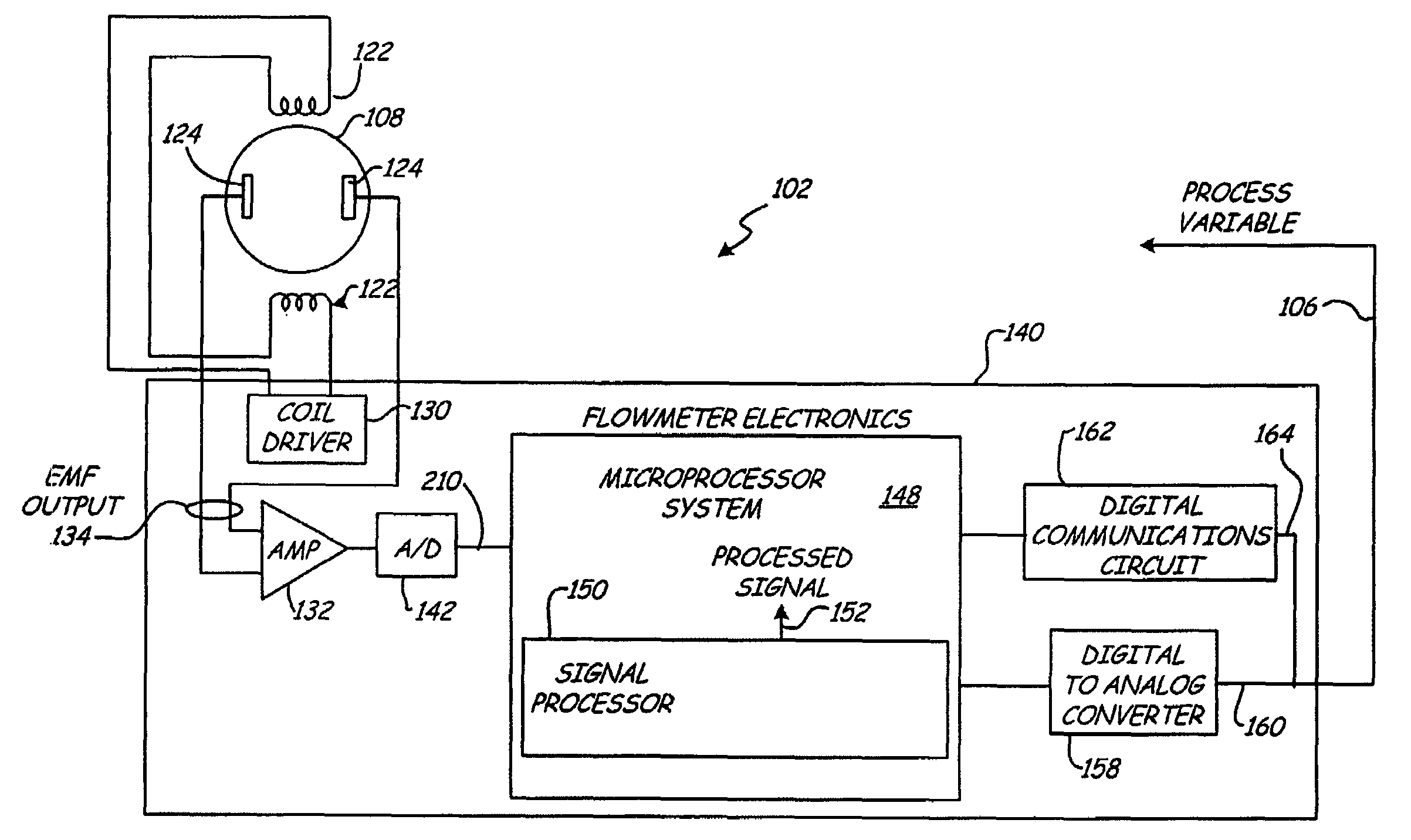
[0014]A magnetic flowmeter and method are provided in which sensitivity to noise is reduced by inverting portions of a fluid voltage signal and / or filtering the fluid voltage signal in accordance with a non-linear filter.

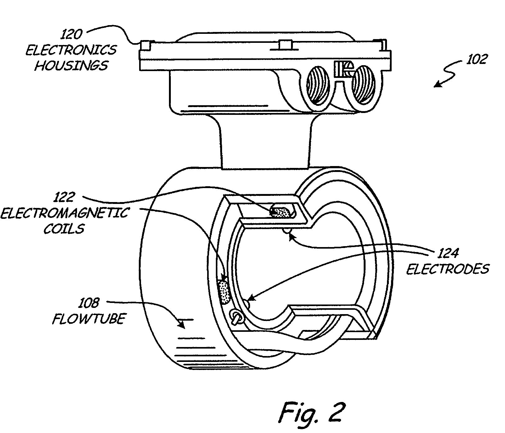
[0015]In FIG. 1, a typical environmental for magnetic flowmeter 102 is illustrated at 100. In FIG. 1, magnetic flowmeter 102 is shown coupled to process piping 104 which also couples to control valve 106. Magnetic flowmeter 102 is an example of one type of process variable transmitter which can be configured to monitor one or more process variables associated with fluids in a process plant such as slurries, liquids, vapors and gases in chemicals, pulp, petroleum, gas, pharmaceutical, food and other fluid processing plants. In a magnetic flowmeter, the monitored process variable relates to velocity of process fluid through flow tube 108. Magnetic flowmeter 102 outputs are configured for transmission over long distances to a controller or indicator via communication b...


PUM


Abstract

A magnetic flowmeter for measuring flow of a process fluid includes a coil configured to apply a magnetic field to the process fluid. Electrodes are arranged to sense a fluid voltage signal related to the applied magnetic field and fluid flow. An analog to digital converter provides a digital output comprising a plurality of digital samples related to the sensed fluid voltage signal. Computation circuitry receives the digitized samples and responsively provides an output related to flow.

Description

BACKGROUND OF THE INVENTION[0001]The present invention relates to magnetic flowmeters that sense liquids flowing in industrial process plants. In particular, the present invention relates to noise detected by electrodes in such magnetic flowmeters.[0002]Magnetic flowmeters utilize an electrically insulated flowtube that carries liquid flowing past an electromagnet and electrodes. The electrodes are carried in the flowtube and make electrical contact with the flowing liquid. The electrodes sense an electromotive force (EMF) which is magnetically induced in the liquid and which is proportional to flow rate of the fluid according to Faraday's law of electromagnetic induction.[0003]Along with this flow EMF, undesired noise is often received from the electrodes of the magnetic flow tube. This electrical noise is indicative of undesired operating conditions associated with the flowing liquid such as poor liquid grounding connections, excessive electrical resistivity in the flowing liquid,...

Claims


Application Information

Patent Timeline
Patent Type & Authority Patents(United States)
IPC IPC(8): G01F1/00G06F19/00
CPCG01F1/60
Inventor FOSS, SCOT R.HUNTER, KIRK A.
Owner MICRO MOTION INC
Learn More