
Transducer array imaging system

a technology of array imaging and transducer, which is applied in the direction of using reradiation, specific gravity measurement, instruments, etc., can solve the problems of large cable, electrical, medical, physical, and electrical difficulties, and achieve ergonomic burden of cabl

Active Publication Date: 2011-12-20
SIEMENS MEDICAL SOLUTIONS USA INC
View PDF83 Cites 53 Cited by
  • Summary
  • Abstract
  • Description
  • Claims
  • Application Information

AI Technical Summary

Benefits of technology

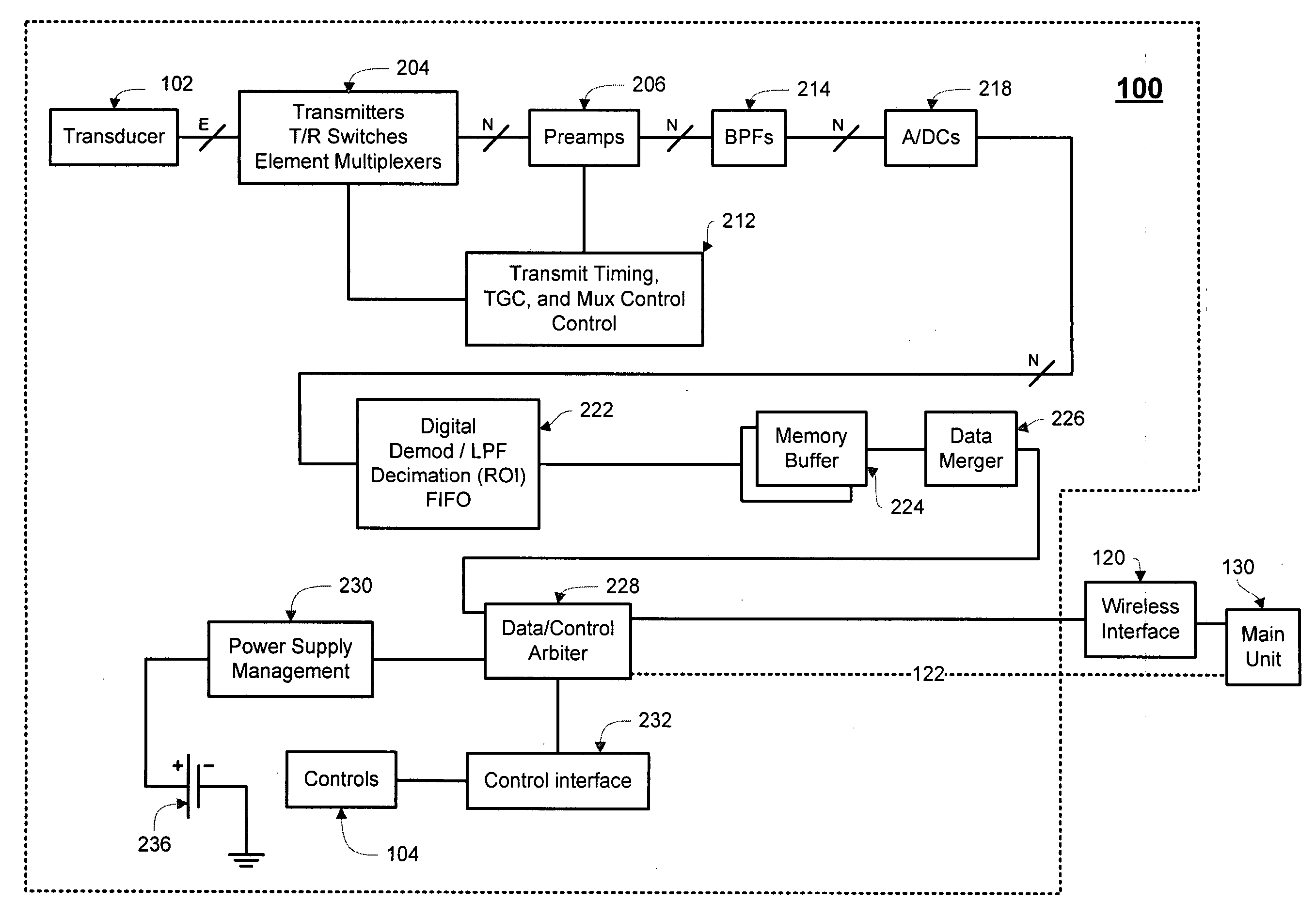
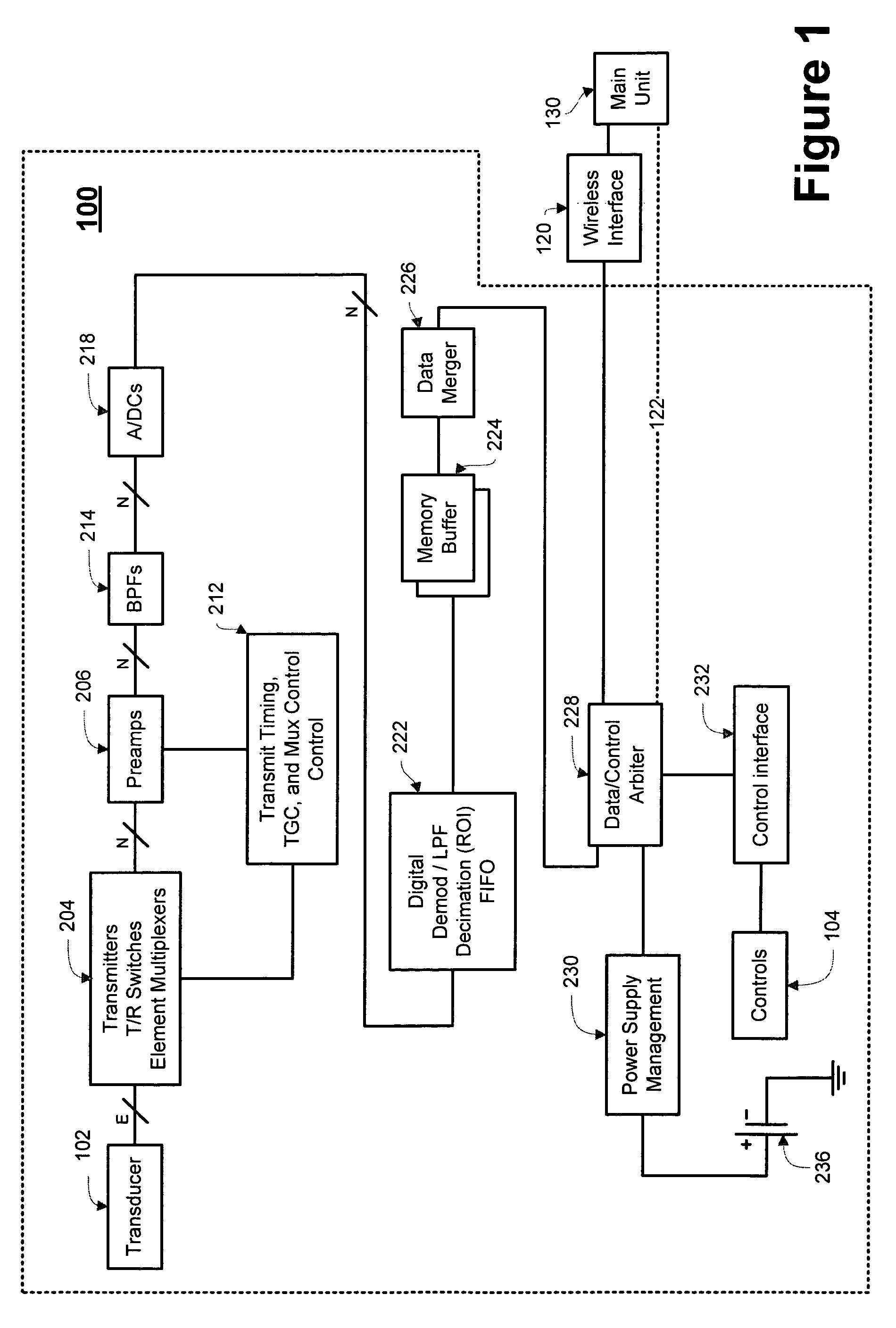
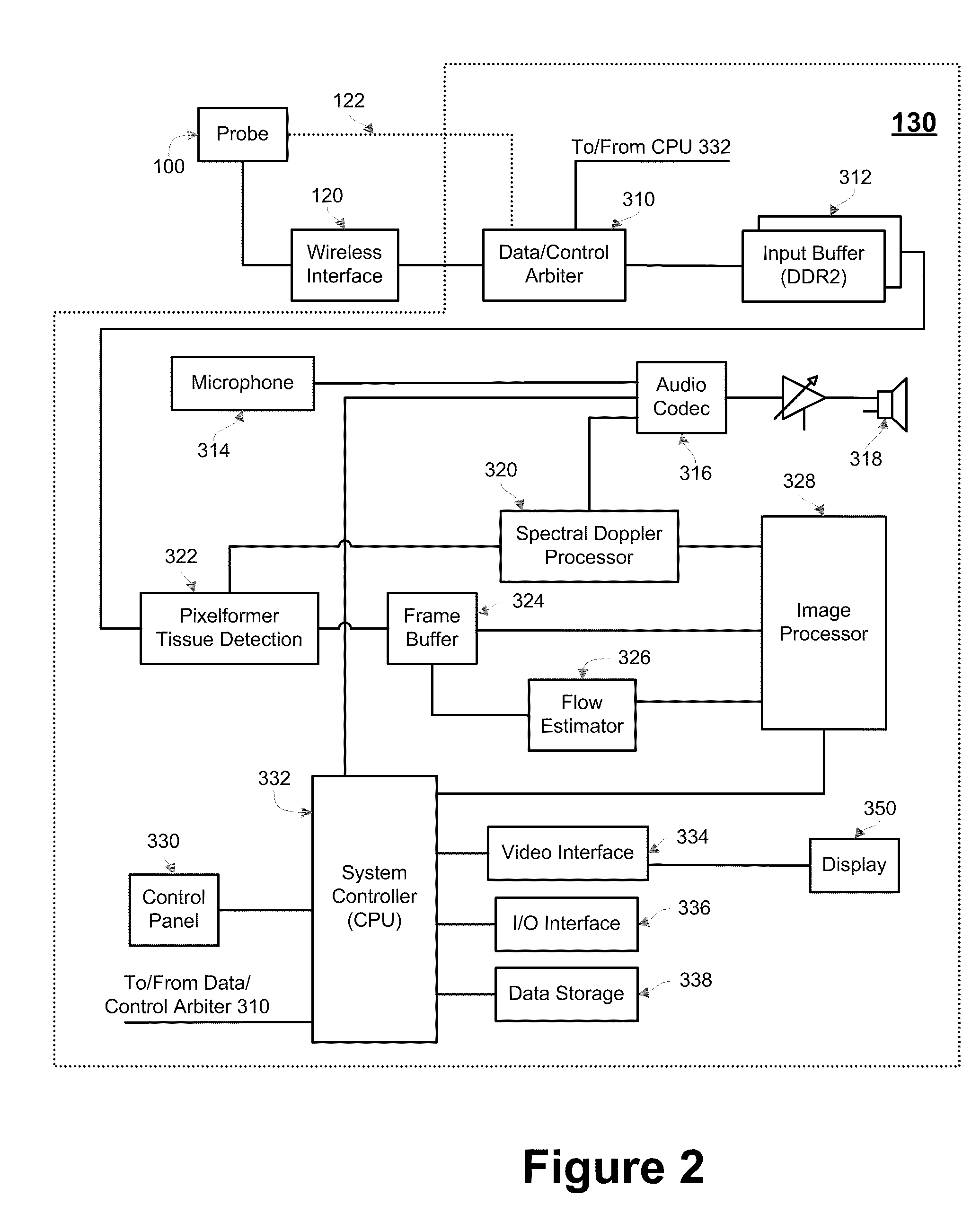
The patent describes a method, system, and device for using ultrasound to interrogate a medium. The method involves transmitting ultrasound waves into the medium and receiving echoed waves that are converted into digital data. The digital data can then be transmitted, either wirelessly. The device includes transducers that convert electrical energy into ultrasound waves, an analog-to-digital converter that converts the echoed waves back into electrical energy, and a transmitter that sends the digital data. The technical effects of this patent include improved methods and devices for ultrasound interrogation of a medium, which can be used in various applications such as medical imaging and non-destructive testing.

Problems solved by technology

Because of the large number of transducer elements typically required, a significant amount of energy is required to be carried by the cable.
The relatively large cable creates difficulties electrically, medically, and physically.
From a physical perspective, for example, the cable is ergonomically burdensome.
Also, the cable capacitance may undesirably result in a lower signal-to-noise ratio (SNR).
From a medical perspective, the cable creates a problem where sterility is an issue.
Once the cable slides out of the sterile field, the necessary sterility is compromised.
As a result, a user is limited in using and moving the cabled probe.

Method used


Image

  • Transducer array imaging system
  • Transducer array imaging system
  • Transducer array imaging system

Examples


Embodiment Construction

h reference to FIG. 16;

[0025]FIG. 18 is a graphical depiction of a total amount of data required from a probe to a main unit with respect to depth of the acceptance angle and edge effects;

[0026]FIG. 19 is an illustration of an example image region of interest for a linear array transducer;

[0027]FIG. 20 is a block diagram employing a ping-pong frame buffer;

[0028]FIG. 21 is a timing diagram illustrating the acquisition of frames of data;

[0029]FIG. 22 is a timing diagram illustrating this frame adjustment; and

[0030]FIG. 23 is a chart representing a sequence of writes and reads to a ping-pong frame buffer.

DETAILED DESCRIPTION

[0031]The subject matter of the described embodiments is described with specificity to meet statutory requirements. However, the description itself is not intended to limit the scope of this patent. Rather, the inventors have contemplated that the claimed subject matter might also be embodied in other ways, to include different steps or elements similar to the ones ...


PUM

PropertyMeasurementUnit
depthaaaaaaaaaa
voltageaaaaaaaaaa
speedaaaaaaaaaa

Abstract

The disclosed embodiments include a method, system, and device for conducting ultrasound interrogation of a medium. The novel method includes transmitting a non-beamformed or beamformed ultrasound wave into the medium, receiving more than one echoed ultrasound wave from the medium, and converting the received echoed ultrasound wave into digital data. The novel method may further transmit the digital data. In some embodiments, the transmitting may be wireless. The novel device may include transducer elements, an analog-to-digital converter in communication with the transducer elements, and a transmitter in communication with the analog-to-digital converter. The transducers may operate to convert a first electrical energy into an ultrasound wave. The first electrical energy may or may not be beamformed. The transducers also may convert an echoed ultrasound wave into a second electrical energy. The analog-to-digital converter may convert the electrical energy into digital data, and the transmitter may transmit the digital data.

Description

CROSS-REFERENCE TO RELATED APPLICATIONS[0001]This application is related to U.S. patent application Ser. No. 11 / 595,674, U.S. patent application Ser. No. 11 / 595,340, U.S. patent application Ser. No. 11 / 595,171, U.S. patent application Ser. No. 11 / 595,729, U.S. patent application Ser. No. 11 / 595,027, U.S. patent application Ser. No. 11 / 595,033, U.S. patent application Ser. No. 11 / 595,706, U.S. patent application Ser. No. 11 / 595,341, U.S. patent application Ser. No. 11 / 595,164, U.S. patent application Ser. No. 11 / 595,335, U.S. patent application Ser. No. 11 / 595,025, U.S. patent application Ser. No. 11 / 595,601, U.S. patent application Ser. No. 11 / 595,334, U.S. patent application Ser. No. 11 / 595,701, U.S. patent application Ser. No. 11 / 595,557, U.S. patent application Ser. No. 11 / 595,336, all filed on Nov. 10, 2006, all entitled “Transducer Array Imaging System,” all commonly owned and all of which are herein incorporated by reference in their entirety, for all purposes.BACKGROUND[0002]...

Claims


Application Information

Patent Timeline
Patent Type & Authority Patents(United States)
IPC IPC(8): G01N29/00G01S15/00
CPCG01S7/5208G01S7/52079G01S7/52073G01S7/003A61B8/4422A61B8/4438A61B8/4483A61B8/4494
Inventor RANDALL, KEVIN S.KLESSEL, JODI SCHWARTZLANNUTTI, ANTHONY P.URBANO, JOSEPH A.WEYMER, JR., RAYMOND F.
Owner SIEMENS MEDICAL SOLUTIONS USA INC
Learn More