
Optical transmitter with SBS suppression

a technology of optical transmitter and suppression, applied in the field of lightwave systems, can solve the problems of sbs permanently damaging the optical fiber, reducing the propagation distance that can be achieved using a carrier signal with increased power in a narrow line width, and increasing the noise detected at the receiver

Inactive Publication Date: 2008-03-25
II VI DELAWARE INC +1
View PDF62 Cites 26 Cited by
  • Summary
  • Abstract
  • Description
  • Claims
  • Application Information

AI Technical Summary

Benefits of technology

The patent text describes a method to improve the transmission of optical signals through optical fibers by reducing the effects of stimulated Brillouin scattering (SBS). SBS is a process that causes noise and damage to the optical signal. The invention aims to increase the bandwidth of the optical signal and reduce amplitude modulation noise to improve transmission quality and increase the possible propagation distance between repeaters. The invention can be applied to optical transmitters, optical receivers, and integrated optical transmitter subassemblies. The technical effect of the invention is to improve the transmission quality and decrease the cost per bit to transmit data and voice information.

Problems solved by technology

The noise detected at the receiver increases as the bandwidth of an individual channel is increased.
However, the propagation distance that can be achieved using a carrier signal with increased power in a narrow line width is severely limited by a physical effect known as stimulated Brillouin scattering (SBS).
In addition, SBS can permanently damage the optical fiber if the optical propagating power is sufficiently high.

Method used


Image

  • Optical transmitter with SBS suppression
  • Optical transmitter with SBS suppression
  • Optical transmitter with SBS suppression

Examples


Embodiment Construction

[0017]Optical fibers used for communications exhibit stimulated Brillouin scattering (SBS) at optical signal power levels that are as low as ˜1 mW in some optical fibers. The threshold optical power that causes SBS can be expressed by the following equation:

Ith≅21(α / GB)

[0018]where the parameter α represents absorption in the optical fiber and the parameter GB represents the peak gain, which is approximately 5×10⁻¹¹ m / W for narrow-bandwidth signals used for communications. The peak gain decreases as the incident optical signal bandwidth increases. For example, an optical fiber having an effective area of 50 μm2, and having an absorption coefficient α≅0.2 dB / km, will exhibit a threshold optical power level which causes SBS that is approximately 2.4 mW for an optical fiber length that is approximately 20 km.

[0019]Optical power levels that exceed the threshold optical power will cause the SBS to rapidly rise until the SBS limits the power that can be transmitted through the optical fibe...


PUM

PropertyMeasurementUnit
frequency shiftingaaaaaaaaaa
frequencyaaaaaaaaaa
lengthaaaaaaaaaa

Abstract

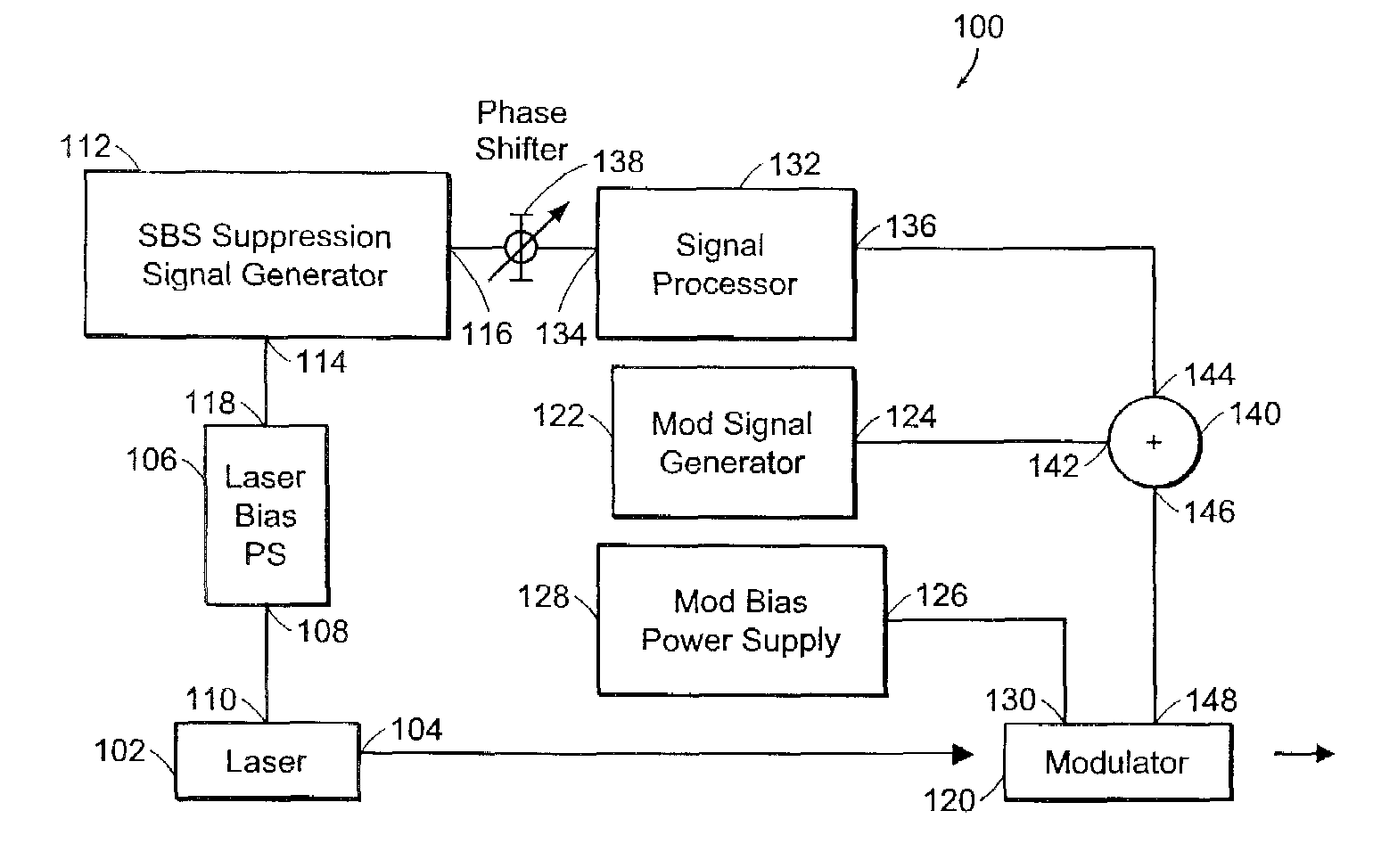
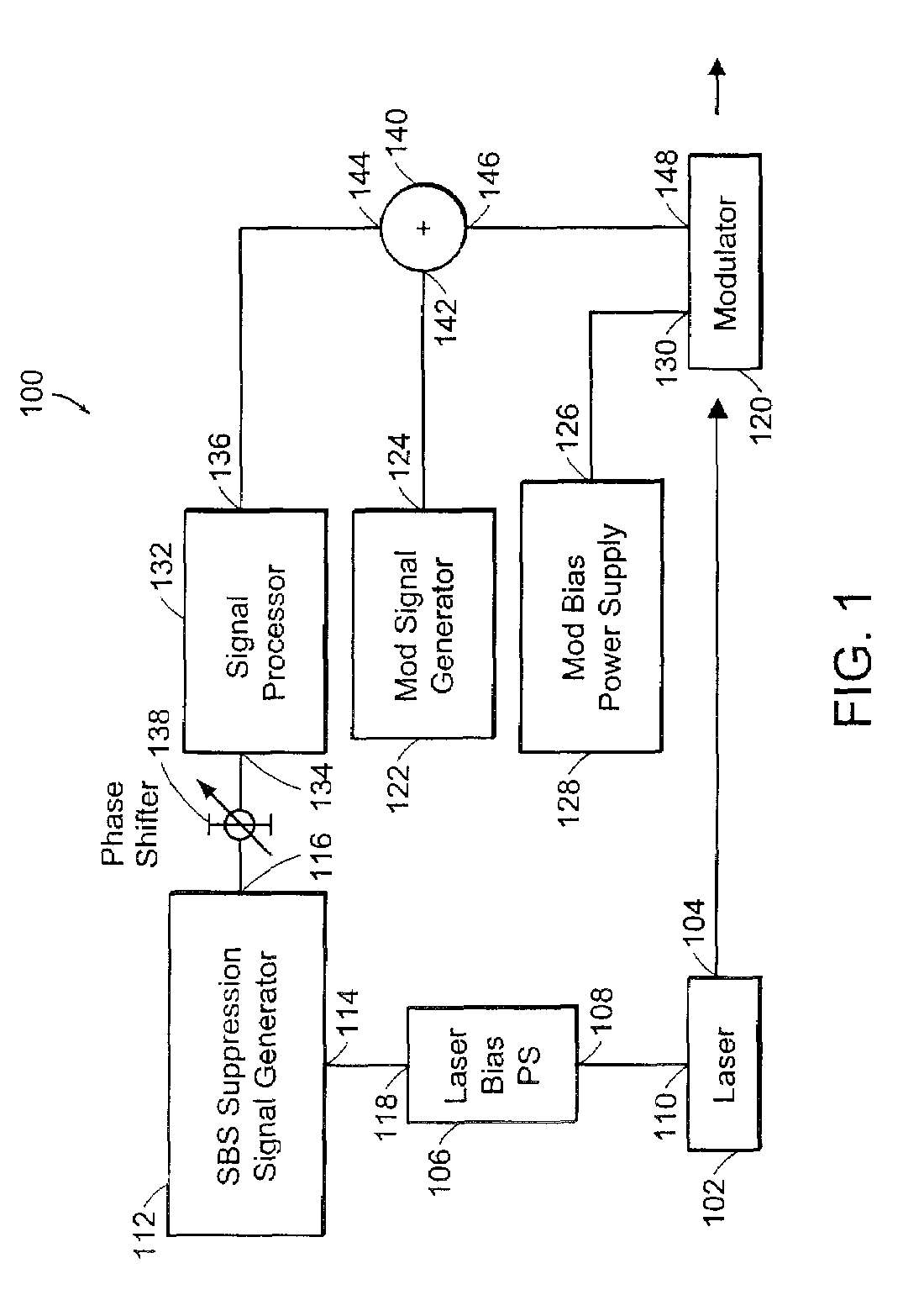
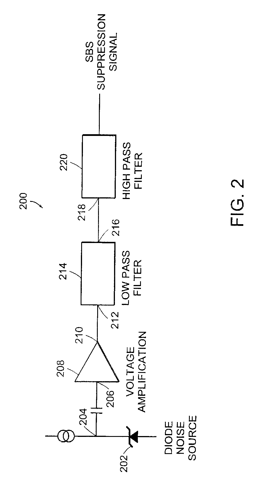
An optical transmitter and methods of generating an optical signal having SBS suppression are described. An optical transmitter having SBS suppression according to the present invention includes a signal generator that generates a SBS suppression signal. A laser generates a line width broadened optical signal having AM noise. A signal processor generates a modified SBS suppression signal from the SBS suppression signal. A modulator modulates the line width broadened optical signal having the AM noise with a payload modulation signal and with the modified SBS suppression signal to generate a payload modulated optical signal having SBS suppression and reduced AM noise.

Description

RELATED APPLICATION SECTION[0001]This application is a continuation application of U.S. patent application Ser. No. 10 / 248,710, filed on Feb. 11, 2003, entitled “Optical Transmitter with SBS Suppression,” the entire application of which is incorporated herein by reference.BACKGROUND OF INVENTION[0002]Optical fiber communication systems are lightwave systems that employ optical fibers to transmit information. Optical fiber communications systems include optical transmitters, optical receivers, and transmission media that propagate information between the optical transmitters and the optical receivers. An optical transmitter for an optical fiber communication system includes an optical source, such as a semiconductor laser, that generates an optical signal and an optical modulator that modulates the optical signal with data or voice information. The modulated optical signal is transmitted through a transmission media, such as an optical fiber, to an optical receiver. The optical recei...

Claims


Application Information

Patent Timeline
Patent Type & Authority Patents(United States)
IPC IPC(8): H04B10/02A46B3/20A46B5/00A46B15/00A46D3/00H04B10/155H04B10/18
CPCA46B3/04A46B3/20A46B5/0029A46B15/0002A46B15/0012A46D1/0207A46D3/005H04B10/2537H04B10/505H04B10/50593H04B10/50597A46B5/002A46B2200/1066A46D1/00H01S2301/03
Inventor FREDERIKSEN, JR., THOMAS R.KRASULICK, STEPHEN B.
Owner II VI DELAWARE INC
Learn More