
Power system for electrically powered land vehicle

a technology of power system and land vehicle, which is applied in the direction of generator/motor, machine/engine, rider propulsion, etc., can solve the problem that the electric force has never been utilized in the conventional electrical energy production system

Active Publication Date: 2008-03-25
GONZALEZ ENCARNACION H
View PDF33 Cites 13 Cited by
  • Summary
  • Abstract
  • Description
  • Claims
  • Application Information

AI Technical Summary

Benefits of technology

The purpose of this invention is to create better parts and ways of putting them together in a way that's cheap, reliable, and works well in electric vehicles.

Problems solved by technology

This patent discusses various methods for creating electrical energy to power vehicles. However, none of these previous solutions involve using electrostatic forces to produce energy. In fact, there was even a time period where it wasn't thought possible to make machines run without traditional mechanical means like engines. The technical problem addressed by this patent is how to develop a powerful power system for electric cars and other land vehicles that can operate efficiently and effectively without relying solely on mechanics.

Method used


Image

  • Power system for electrically powered land vehicle
  • Power system for electrically powered land vehicle
  • Power system for electrically powered land vehicle

Examples


Embodiment Construction

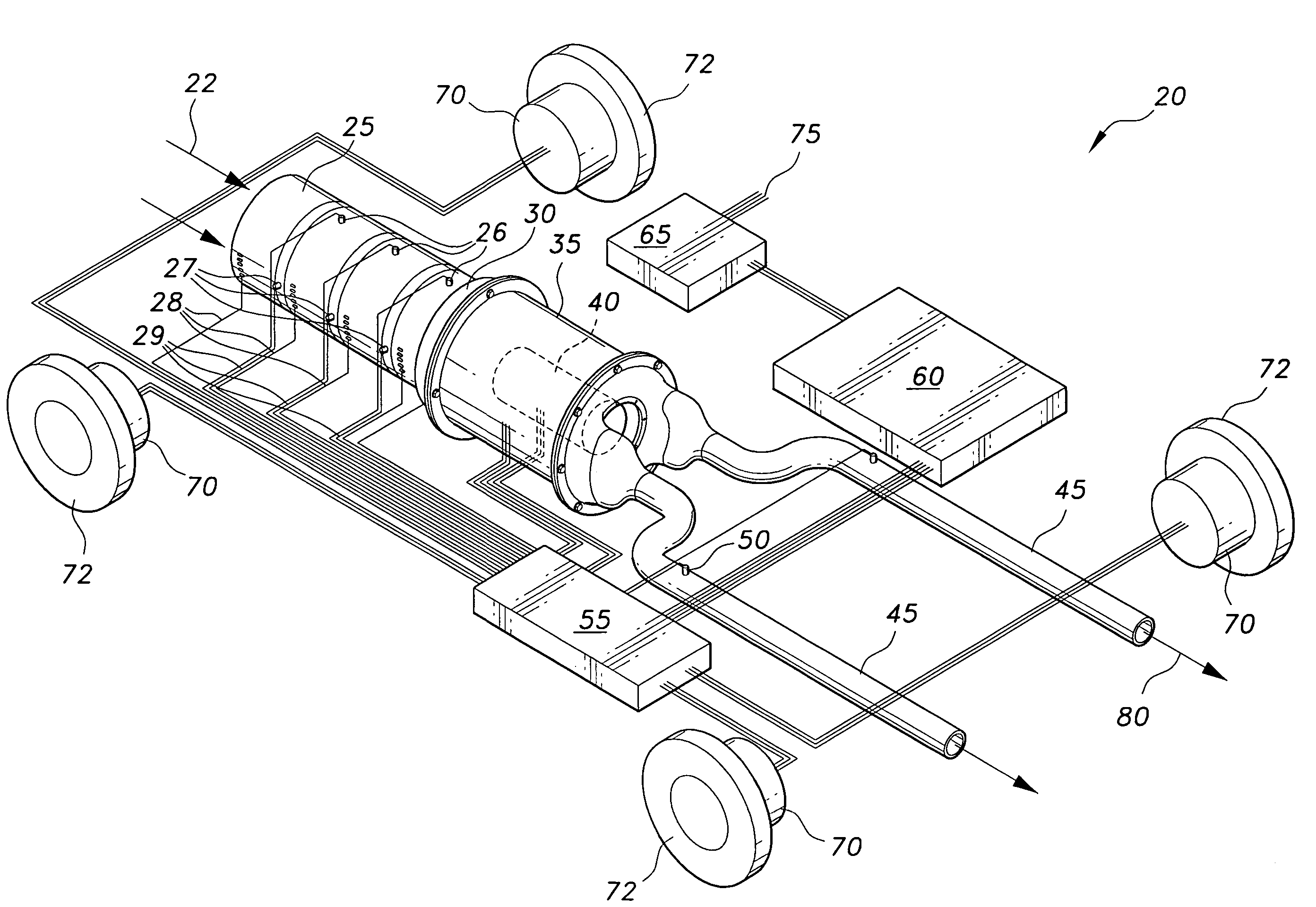
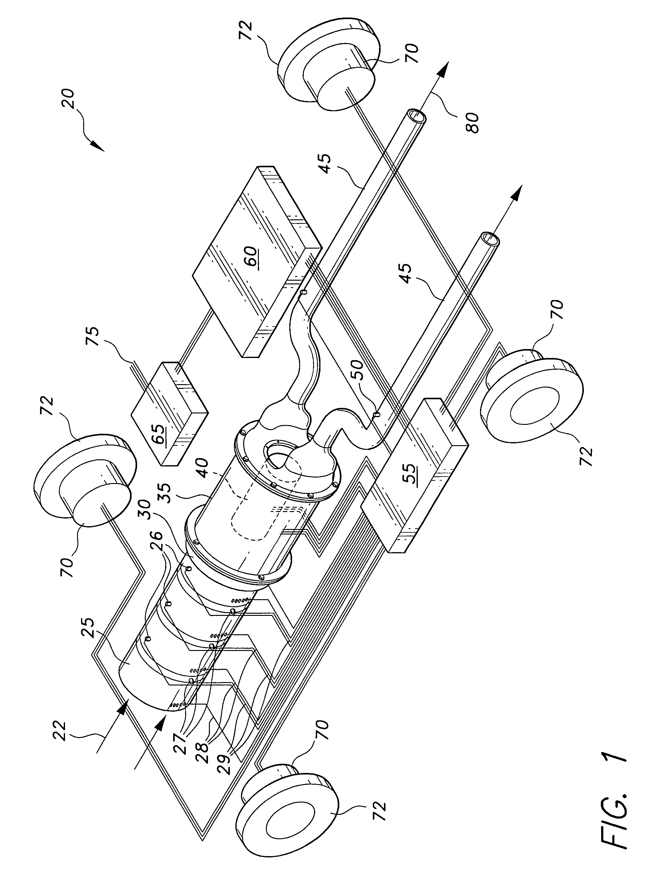
[0043]The present invention is directed to a power system for an electrically powered land vehicle, generally designated as 20 in the drawings. The power system 20 of the present invention provides an alternate energy source for wheeled land vehicles. The power system 20 uses electrons extracted from the ambient air to generate electrical power sufficient to operate a wheeled land vehicle. The power system 20 is designed to produce more than sufficient electric power to run an electric vehicle propulsion system and all accessory electric systems, including air conditioning, stereo / radio, electric heating, AC output from a power inverter, windshield wiping systems, etc.

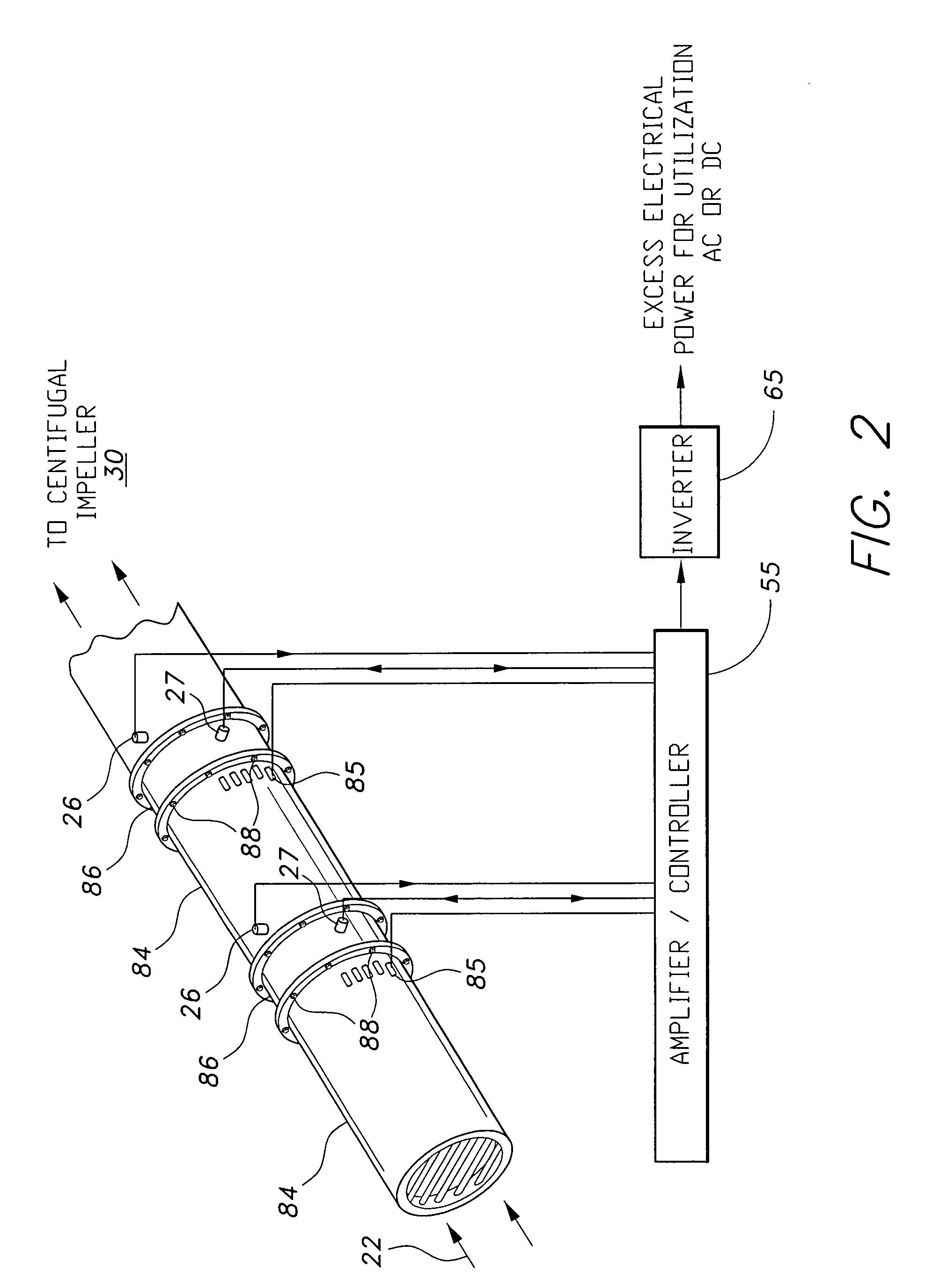
[0044]FIG. 1 shows a diagrammatic view of the basic components required to produce electrical power from ambient air in order to power a wheeled land vehicle. The power system 20 includes a gas ionization and energy production section 25, similar to the electrical energy production system disclosed in the inventor's pr...


PUM


Abstract

The power system for an electrically powered land vehicle extracts electrons from ambient air to generate adequate electrical power to operate the land vehicle electrical energy production and propulsion system. The extracted electrons generate enough electrical power to run an electrical propulsion system and all accessory electrical systems of the land vehicle. The power system includes an abutting series of tubular sections defining an airflow path with a heating plates in the airflow path and variable positive voltage grids to extract charged particles from the heated air. Air is drawn into the airflow path by a centrifugal impeller. The ionized air not used to generate electric power is neutralized in an ionized gas neutralizing chamber and then exhausted.

Description


Claims


Application Information

Patent Timeline
Owner GONZALEZ ENCARNACION H
Learn More