
Developing apparatus

a technology of developing apparatus and developing electrode, which is applied in the direction of electrographic process apparatus, instruments, optics, etc., can solve the problems of inability to eliminate density differences, difficult to immediately reach the proper charge of toner, and small effect of ghosting phenomenon, so as to prevent unfavorable density and ghosting image

Inactive Publication Date: 2008-03-18
CANON KK
View PDF9 Cites 3 Cited by
  • Summary
  • Abstract
  • Description
  • Claims
  • Application Information

AI Technical Summary

Benefits of technology

The present invention provides a developing apparatus that can improve the uniformity of toner charging, prevent uneven density, and prevent ghost images. Additionally, the developing characteristic of the apparatus can be stabilized during the early stages of use and later stages of use.

Problems solved by technology

Now, in a new (unused) developing apparatus, the toner in a developer container has charges not imparted thereto and therefore, even if charges are imparted by that portion of the developing blade which abuts against the developing sleeve, it is difficult for the proper charges of the toner to be immediately reached.
There is also means for detecting only the early stage of the use of the developing apparatus and changing the setting of the developing bias of the image forming apparatus main body to a side for enhancing the developing property to thereby heighten the density, but by this means, it is impossible to eliminate the density difference between the first one revolution and the second and subsequent revolutions of the developing sleeve, and the effect for the ghost phenomenon is small.
This means was very effective against the negative ghost, but it has been found by the inventor's repeated study that when a toner having relatively high chargeability is used, a faulty image such as white haze or a longitudinal streak may occur.

Method used


Image

  • Developing apparatus
  • Developing apparatus
  • Developing apparatus

Examples


embodiment 1

[0034]Embodiment 1 of the present invention will hereinafter be described with reference to the drawings.

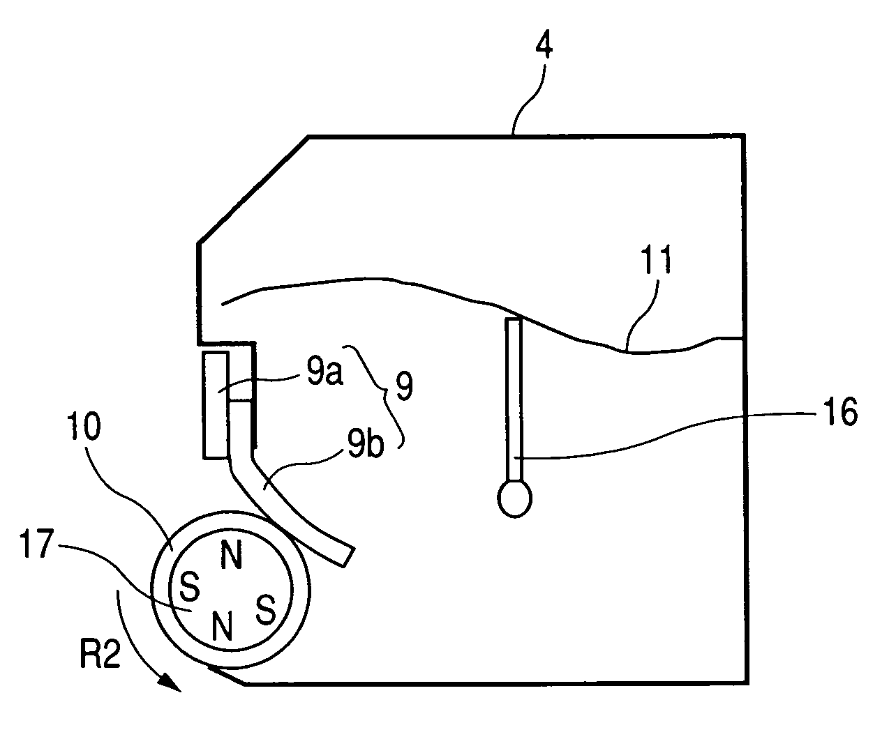
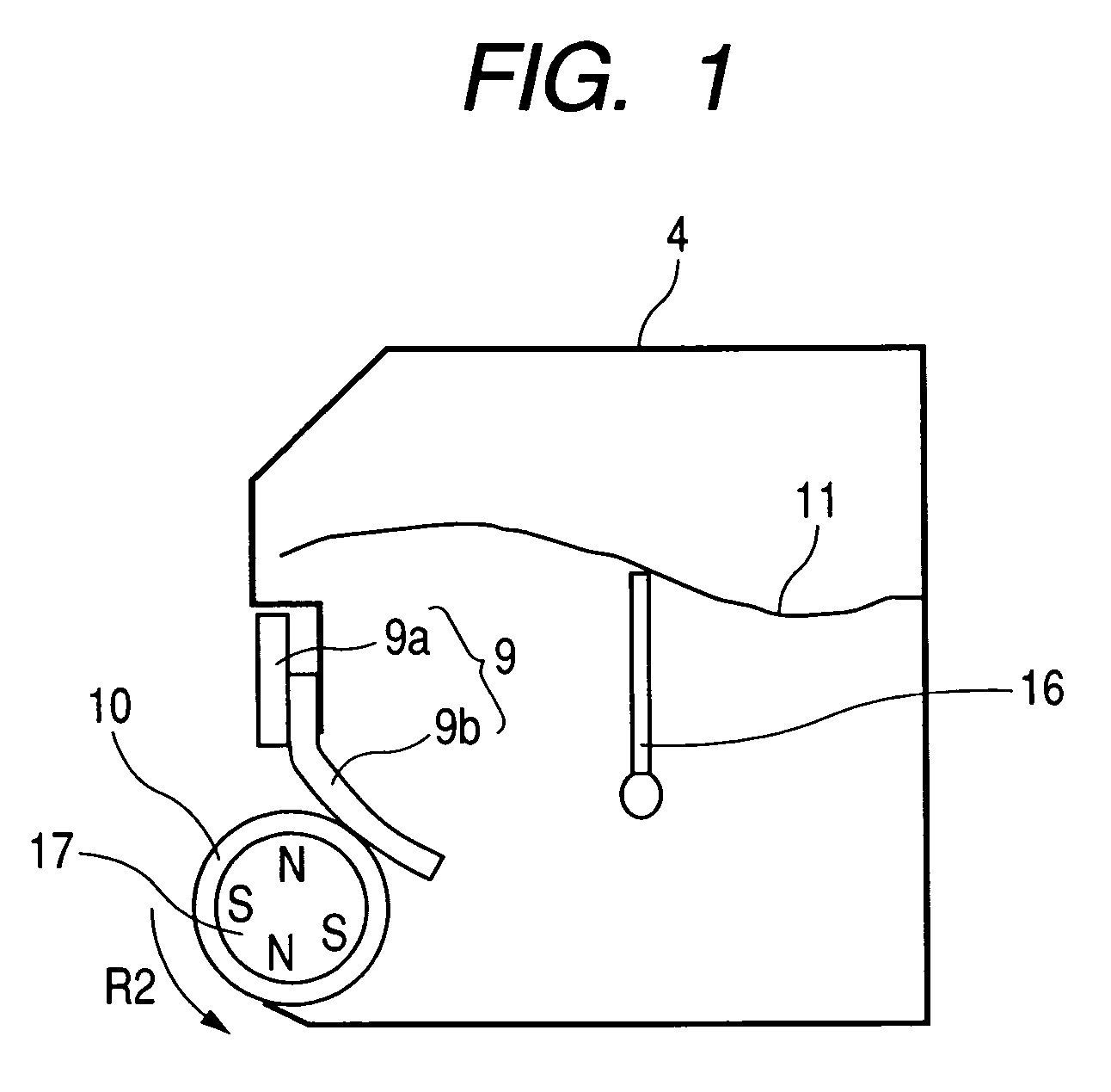
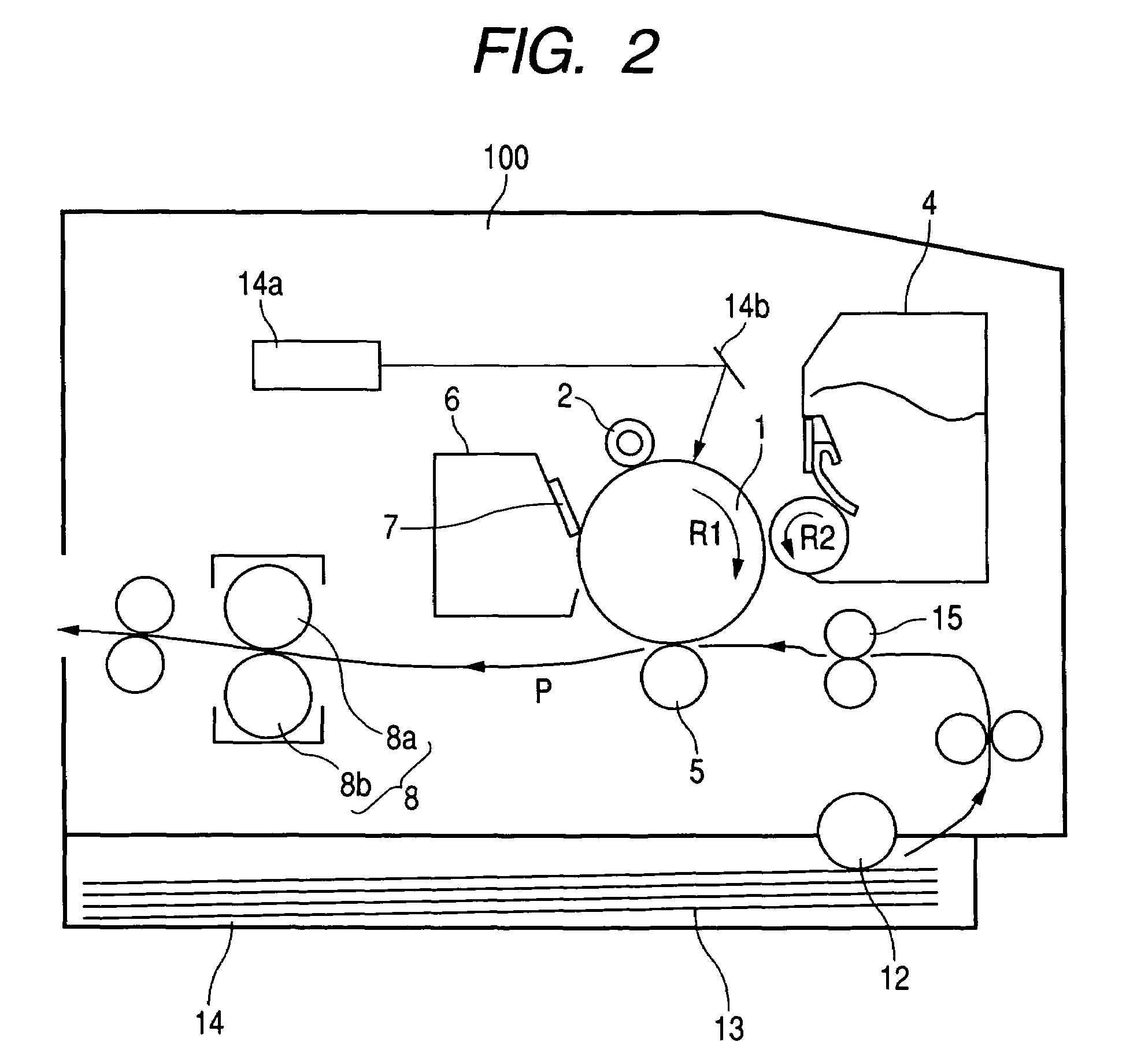
[0035]FIG. 1 shows an example of a developing apparatus according to Embodiment 1 of the present invention. FIG. 1 is a longitudinal cross-sectional view schematically showing the construction of the developing apparatus. FIG. 2 shows an example of an image forming apparatus according to the present embodiment provided with this developing apparatus. FIG. 2 is a longitudinal cross-sectional view schematically showing the construction of the image forming apparatus.

[0036]Reference is first made to FIG. 2 to describe the entire image forming apparatus, and then reference is made to FIG. 1 to describe the developing apparatus.

[0037]The image forming apparatus shown in FIG. 2 is provided with an image forming apparatus main body (hereinafter referred to as the apparatus main body) 100 as a printer engine.

[0038]A drum-shaped electrophotographic photosensitive member (hereinafter refer...

embodiment 2

[0099]Embodiment 2 of the present invention will hereinafter be described. An image forming apparatus according to this embodiment is similar in construction to the image forming apparatus according to Embodiment 1 described above, and need not be described.

[0100]In the present embodiment, description will be made of a combination of a toner having a high degree of circularity and a lubricant, and the inventor has confirmed as a result of his study that the higher is the degree of circularity of the toner, the more is obtained the effect of the present invention.

[0101]The toner having a high degree of circularity is a toner of which the weight average particle diameter X is 5-12 μm, and which has particles having a circle-corresponding diameter of 3 μm or greater and a degree of circularity of 0.900 or greater by 90% or more in terms of a cumulative value based on the particle number standard, and in which the relation between the particle number cumulative standard value Y of parti...


PUM


Abstract

A developing apparatus having a developer carrying member carrying developer including toner, a developer regulating member regulating the layer thickness of the developer carried on the developer carrying member, and a lubricant provided in a contact portion between the carrying member and the regulating member with the developer being not present on the carrying member, wherein the lubricant includes a first polymer particle which is of a spherical shape having an average degree of circularity of 0.90 or greater and is of a polarity opposite to the charging polarity of the toner, and a second polymer particle of a scalelike shape and of the same polarity as the charging polarity of the toner.

Description

BACKGROUND OF THE INVENTION[0001]1. Field of the Invention[0002]The invention relates to a developing apparatus usable in an image forming apparatus such as a copying machine, a printer or a facsimile apparatus.[0003]2. Description of the Related Art[0004]An image forming apparatus adopting a conventional electrophotographic printing method will first be described with reference to FIG. 4 of the accompanying drawings.[0005]As shown in FIG. 4 of the accompanying drawings, a popular image forming apparatus comprises a photosensitive member 101 as a rotatable latent image bearing member, a charging device 102 driven to rotate by the photosensitive member 101 for charging the photosensitive member 101 to predetermined potential, an exposing device 103 for forming an electrostatic latent image on the photosensitive member 101, a developing apparatus 104 for developing and visualizing the electrostatic latent image on the photosensitive member 101, a transferring device 105 for transferri...

Claims


Application Information

Patent Timeline
Patent Type & Authority Patents(United States)
IPC IPC(8): G03G15/09
CPCG03G15/0812G03G2215/0609G03G2215/0634
Inventor INAMI, SATORUBABA, DAISUKEKATO, MASAHITO
Owner CANON KK
Learn More