Optical element holding structure, optical element lens-barrel and optical communication module
a technology of optical elements and holding structures, applied in the field of optical element holding structures, optical element lensbarrels and optical communication modules, can solve the problems of internal double refraction, optical axis shifting, double refraction phenomenon, etc., and achieve the effect of controlling the deterioration of optical properties and preventing the shifting of optical axis
- Summary
- Abstract
- Description
- Claims
- Application Information
AI Technical Summary
Benefits of technology
Problems solved by technology
Method used
Image
Examples
first embodiment
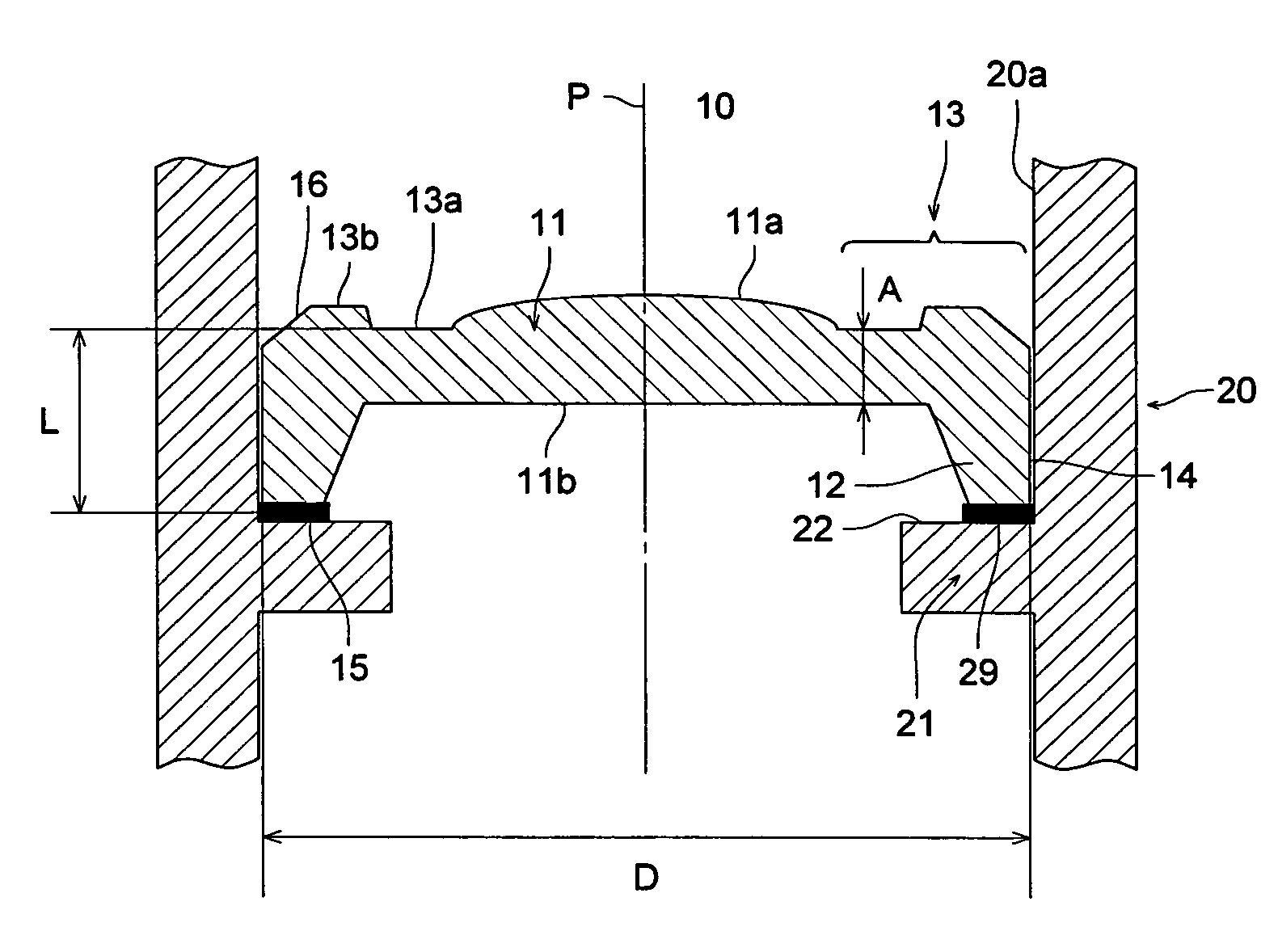
[0066]FIG. 1 is a main part vertical portion showing the lens holding structure of the first embodiment. The lens holding structure shown in FIG. 1 fixes and holds a lens 10 onto the inner surface 20a of a cylindrical lens barrel 20 using a bonding agent.
[0067]The lens 10 is made up of a lens portion 11 which has a lens function; an outer peripheral portion 13 which is positioned on the outer peripheral side of the lens portion 11 and extends to the outermost periphery 14 of the lens 10; and a mounting portion 12 which protrudes from the outer peripheral portion 13 in a direction substantially parallel to the optical axis p, and is a plastic lens which is formed from a resin for optical elements. The lens 11 has a convex portion 11a which is the center of the optical axis p, and the flat surface 11b which at the opposite side of the convex portion 11a extends from the lens portion 11 to a part of the outer peripheral portion 13. The stress reducing section is formed from the outer p...
second embodiment
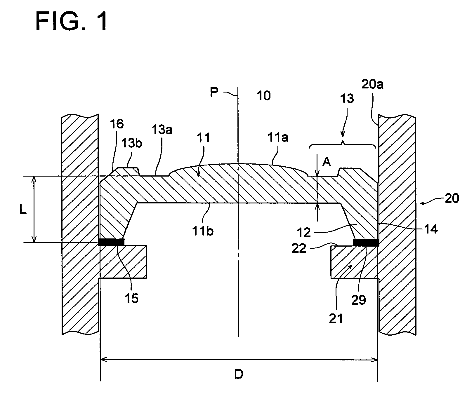
[0078]FIG. 2 is a main part vertical portion showing the lens holding structure of the second embodiment. The lens holding structure shown in FIG. 2 fixes and holds a lens 30 onto an inner surface 4.0a of a lens barrel 40 using a step structure.
[0079]As shown in FIG. 2, compared to the lens 10 of FIG. 1, the lens 30 is has substantially the same structure as that of FIG. 1 except for the fact that the mounting portion protrudes from the outer peripheral portion 13 in the direction substantially-parallel to the optical axis p has a step portion 36 which protrudes further out than the outermost periphery 14 of the lens 30 at the lower side that is opposite to the convex portion 11a of the lens portion 11. As a result, the parts that are the same have been assigned the same numbers and descriptions thereof have been omitted.
[0080]In addition the lower portion in FIG. 2 of the inner surface 40a of the lens barrel 40 is formed at an inner surface portion 41 having an inner diameter that ...
third embodiment
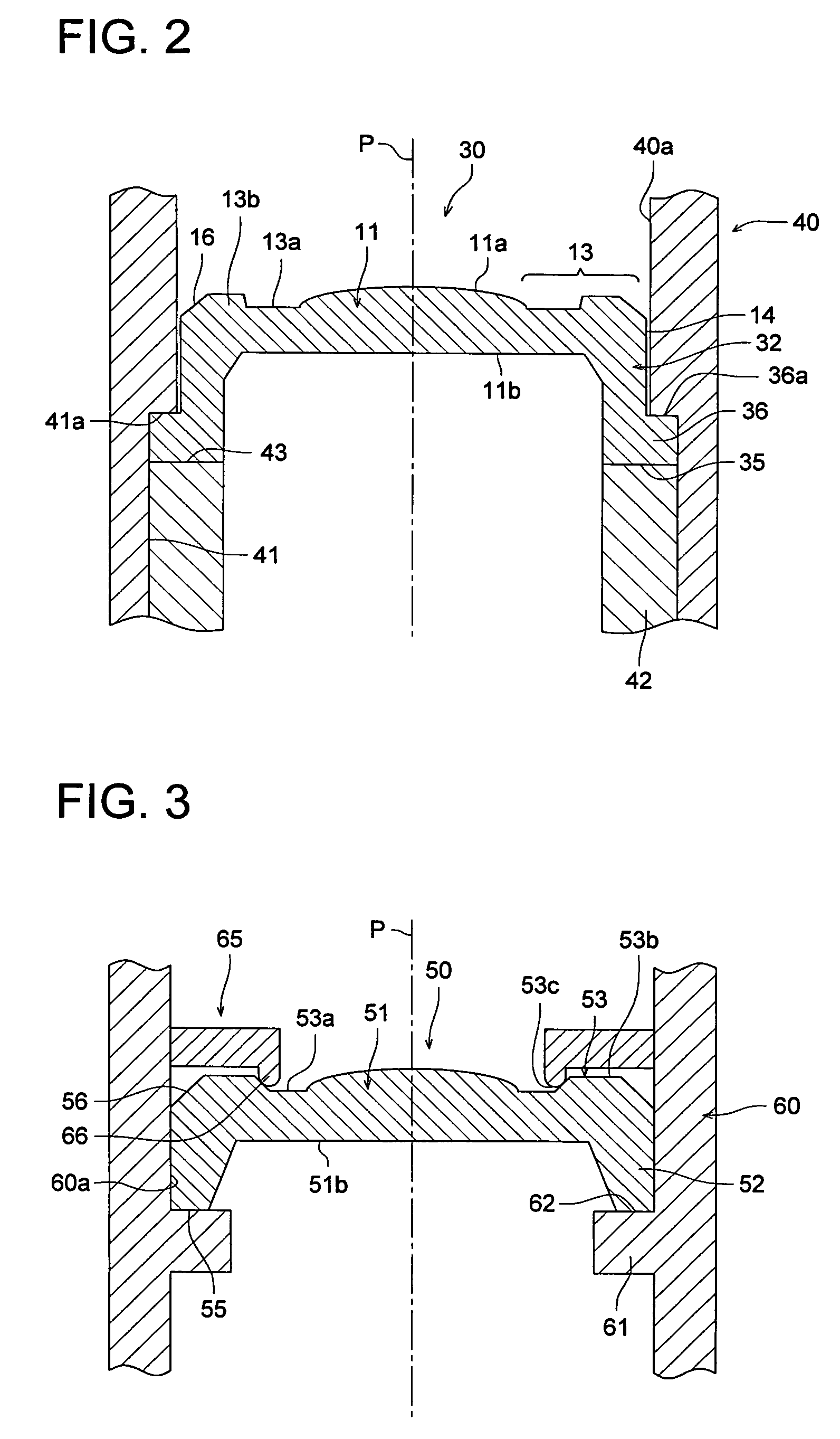
[0086]FIG. 3 is a main part vertical portion showing the lens holding structure of the third embodiment. The lens holding structure shown in FIG. 3 holds a lens 50 onto the inner surface 60a of a cylindrical lens 60 using the ring-like member 65.
[0087]The lens 50 is made up of a lens portion 51 which has a lens function; an outer peripheral portion 53 which is positioned on the outer peripheral side of the lens portion 51 and extends to the outermost periphery 54 of the lens 50; and a mounting portion 52 which protrudes from the outer peripheral portion 53 in a direction substantially parallel to the optical axis p, and is a plastic lens which is formed from a resin for optical elements. The lens 51 has a convex portion 51a which is the center of the optical axis p and a flat surface 51b which at the opposite side from the convex portion 51a extends from the lens portion 51 to a part of the outer peripheral portion 53.
[0088]The mounting portion 52 extends so as to form a leg portion...
PUM
 Abstract
Description
Claims
Application Information
 - R&D
- Intellectual Property
- Life Sciences
- Materials
- Tech Scout
- Unparalleled Data Quality
- Higher Quality Content
- 60% Fewer Hallucinations
Browse by: Latest US Patents, China's latest patents, Technical Efficacy Thesaurus, Application Domain, Technology Topic, Popular Technical Reports.
© 2025 PatSnap. All rights reserved.Legal|Privacy policy|Modern Slavery Act Transparency Statement|Sitemap|About US| Contact US: help@patsnap.com


