
Synchronization method and control system for the time synchronization of slave units and a synchronizable slave unit

a technology of time synchronization and control system, which is applied in the direction of programme control, instruments, transmission, etc., can solve the problems of individual timer deviation, and achieve the effect of improving the time synchronization of control units

Inactive Publication Date: 2008-03-11
BOSCH REXROTH AG
View PDF7 Cites 5 Cited by
  • Summary
  • Abstract
  • Description
  • Claims
  • Application Information

AI Technical Summary

Benefits of technology

"The present invention provides an improved method for synchronizing control units in a control system. This method involves using a master unit to control multiple slave units, with each slave unit having two signal lines that pass through it. The master unit sends a reference signal to each slave unit, and the slave units perform time synchronization by comparing the reference signal with the signal through time. The method includes steps of ascertaining the signal through time by each slave unit and reporting it to the master unit. The master unit sends at least one control signal to all slave units as a reference signal. Each slave unit has a time counter to perform the synchronization. The invention also provides a control system as well as a time-synchronizable slave unit. The method and system allow for efficient and automatic synchronization of control units, with low data transfer volume between the master unit and the slave units."

Problems solved by technology

One disadvantage of this traditional method is that after ascertaining the transit time difference, each slave unit must calculate the individual signal transit time of the individual communication paths.
Because of the limited accuracy of such timers, a deviation among the individual timers may develop within a short period of time and may be substantial in comparison with the required timing precision.
One disadvantage of this method is that it requires an extensive initialization phase during which the central control unit determines the signal transit time to each node and sends this information to the individual nodes.

Method used


Image

  • Synchronization method and control system for the time synchronization of slave units and a synchronizable slave unit
  • Synchronization method and control system for the time synchronization of slave units and a synchronizable slave unit
  • Synchronization method and control system for the time synchronization of slave units and a synchronizable slave unit

Examples


Embodiment Construction

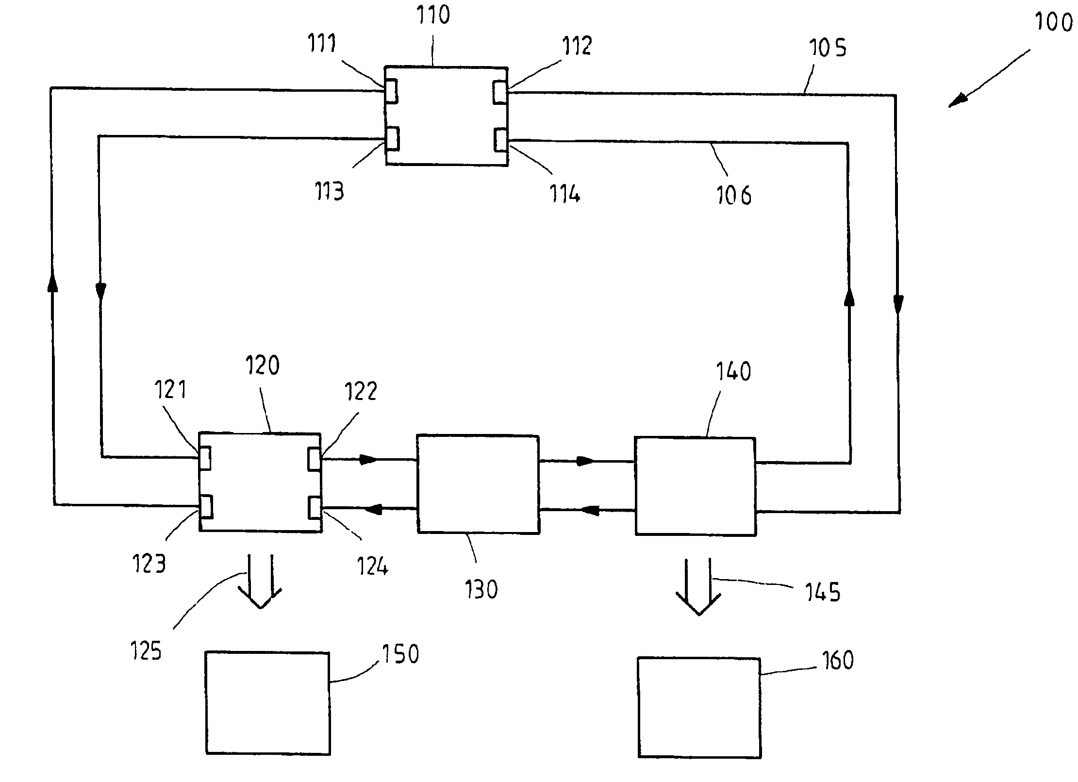
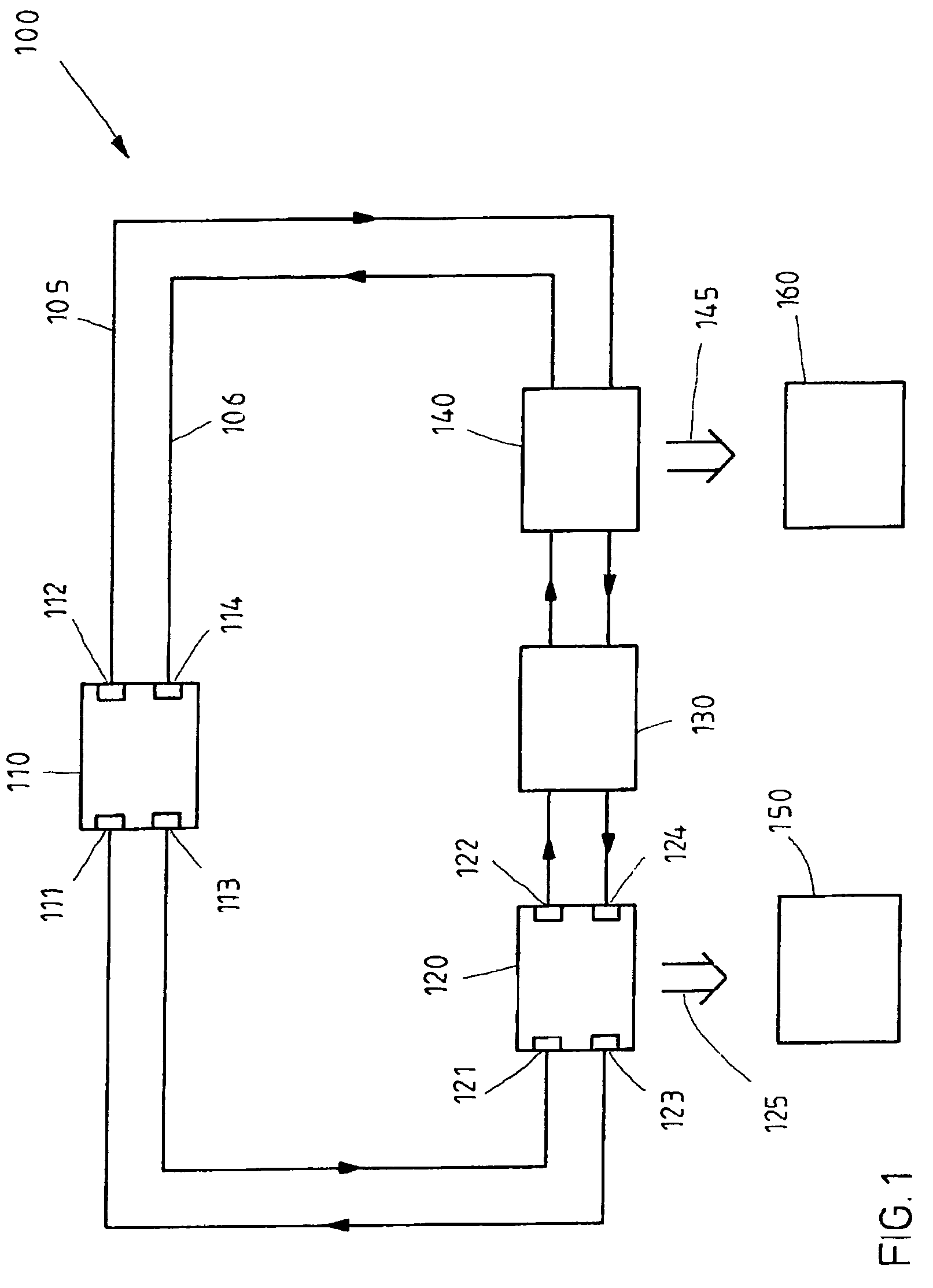
[0051]FIG. 1 schematically shows the design of the control system according to the exemplary embodiment and / or exemplary method of the present invention in a first embodiment. The control system shown here has a master unit 110 which is designed to control multiple slave units 120, 130 and 140. FIG. 1 shows three such slave units. The control system according to the present invention has at least two slave units, but it may also include a much larger number of slave units.

[0052]The slave units generate synchronization signals or control signals 125, 145 having high time precision to operate system components of a controlled system, indicated here schematically by reference numerals 150 and 160, on the basis of a common time base. If the controlled system is a printing machine, for example, then subunits 150 and 160 are typically printing stations having the corresponding drives and control units.

[0053]Master unit 110 and slave units 120, 130 and 140 are interconnected by two signal ...


PUM


Abstract

A synchronization method, a control system and a slave unit for the time synchronization of at least two slave units, in which the slave units and the master unit are connected by two signal lines. A signal transmitted by the master unit returns to the master unit after passing through all the slave units. Two independent counters are provided in each slave unit, these counters being activated by reception of a reference signal transmitted by the master unit. The first time counter counts the time since the receipt of the reference signal via the first signal line and the second time counter counts the time since the receipt of the reference signal via the second signal line. The counter contents are read out as soon as the sum of the counter contents reaches a signal throughput time transmitted previously by the master unit.

Description

RELATED APPLICATION INFORMATION[0001]The present application is based on priority German patent application no. DE 10 2004 055 975.9, which was filed in the German patent office on Nov. 19, 2004, and the entire contents of which are hereby incorporated by reference.FIELD OF THE INVENTION[0002]The present invention relates to a method and a control system for the time synchronization of multiple slave units which are controlled by a master unit via a communication system. In particular, the exemplary embodiment and / or exemplary method of the present invention relates to a method and a control system that outputs synchronization signals to multiple slave units in a synchronized manner. Finally, the exemplary embodiment and / or exemplary method of the present invention relates to a synchronizable slave unit.BACKGROUND INFORMATION[0003]To control industrial processes and systems, e.g., offset printing machines and machine tools, it is often necessary to control, i.e., drive, a plurality ...

Claims


Application Information

Patent Timeline
Patent Type & Authority Patents(United States)
IPC IPC(8): G06F13/00G06F1/12
CPCH04J3/0661H04J3/0682G05B2219/25478
Inventor KYNAST, RIGOBERTSCHNEIDER, BERNARD
Owner BOSCH REXROTH AG
Learn More