
Robot apparatus and load sensor

a robot and load sensor technology, applied in adaptive control, program control, instruments, etc., can solve the problems of complex mechanism, inability to control the posture and walking of bipedal robots, and inability to move in a stable position, etc., to achieve simple structure, high accuracy, and easy to design

Active Publication Date: 2008-03-11
SONY CORP +1
View PDF2 Cites 9 Cited by
  • Summary
  • Abstract
  • Description
  • Claims
  • Application Information

AI Technical Summary

Benefits of technology

[0016]It is therefore an object of the present invention to overcome the above-mentioned drawbacks of the related art by providing a load sensor that will not be broken even when applied with a large load, has a simple structure, is easy to be designed lightweight and compact and can detect a load with a high accuracy, and a legged robot apparatus having the load sensor provided in each leg.
[0024]In the above robot apparatus according to the present invention, since the pressing member having a stopper function to limit the external force to below the predetermined threshold, to thereby making the external force smaller than the predetermined threshold, so the detecting accuracy of the load sensor can be maintained by preventing the pressure detecting means of the load sensor provided in the moving means from incurring a permanent deformation or being broken, for example, when the robot apparatus moves. Also, since the pressure detecting means is pressed by the pressing member that is deformed correspondingly to the magnitude of the external force, it is possible to detect the external force with an extremely high accuracy and stability.
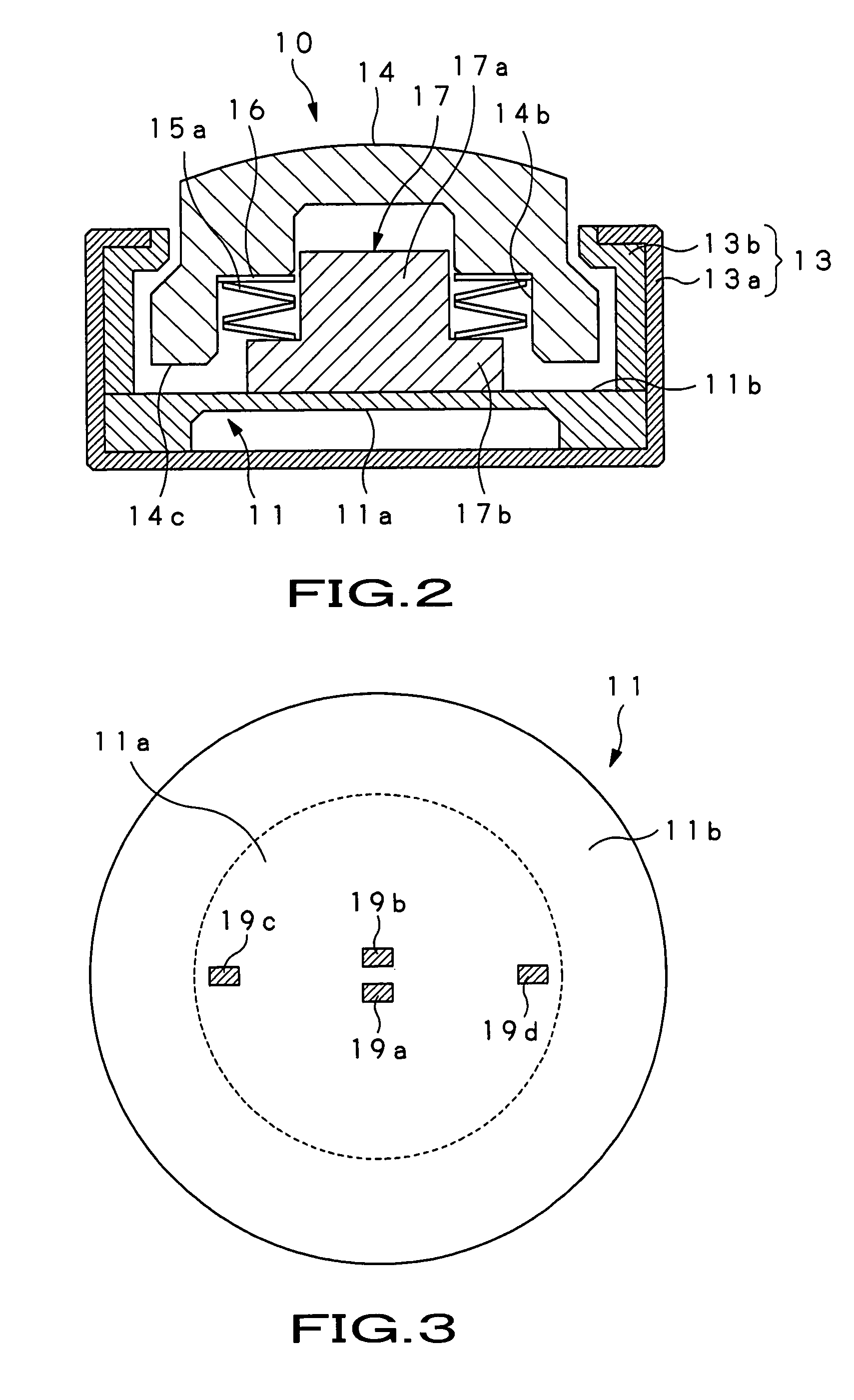
[0032]Furthermore, the driving member may have a flange portion that abuts the pressure-sensitive portion, the activating member may have a step portion that presses the driving member, and the elastic member may be a belleville spring (coned disk spring) that is engaged on each of the flange and step portion to couple the driving and activating members to each other. By using a belleville spring as the elastic member as above, it is possible to displace the elastic member linearly even when the length of the elastic member in which it displaces is reduced.
[0033]As above, in the robot apparatus according to the present invention, the load sensor including the pressing member incorporating the stopper function and which displaces in proportion to the magnitude of an external force is provided in each of the moving means of the robot apparatus, especially, in the moving foot. The pressing member prevents the pressure detecting means of the load sensor from incurring a permanent deformation or being broken, for example, and maintains the accuracy of external force detection by pressing the pressure detecting means correspondingly to the magnitude of an external force. Thus, according to the present invention, the robot apparatus can be designed lightweight and compact and manufactured at a low cost, and also there can be provided a robot apparatus having a foot sole incorporating a ZMP measurement function and which is highly resistant against an impact.
[0034]In the load sensor according to the present invention, since the pressure detecting means can be pressed with a generally constant load by the pressing member whose stroke is generally proportional to a load applied, not depending upon any environmental condition, the load can be detected accurately. Also, the stopper function provided in the load sensor to limit a pressure to below a predetermined threshold can prevent the pressure detecting means from being broken by an excessive or impact load.

Problems solved by technology

In the meantime, the bipedal robot apparatuses walking in erect posture are not so stable as a crawler-, quadruped- and hexapod-type ones and control of their posture and walking needs a complicated mechanism.
In other words, the space where the human being is living includes too many barriers against the current mechanical system using wheels and other drive units as a moving means.
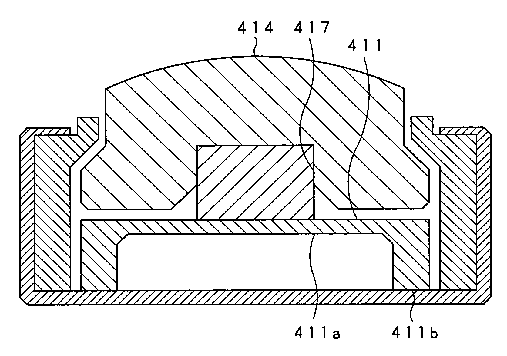
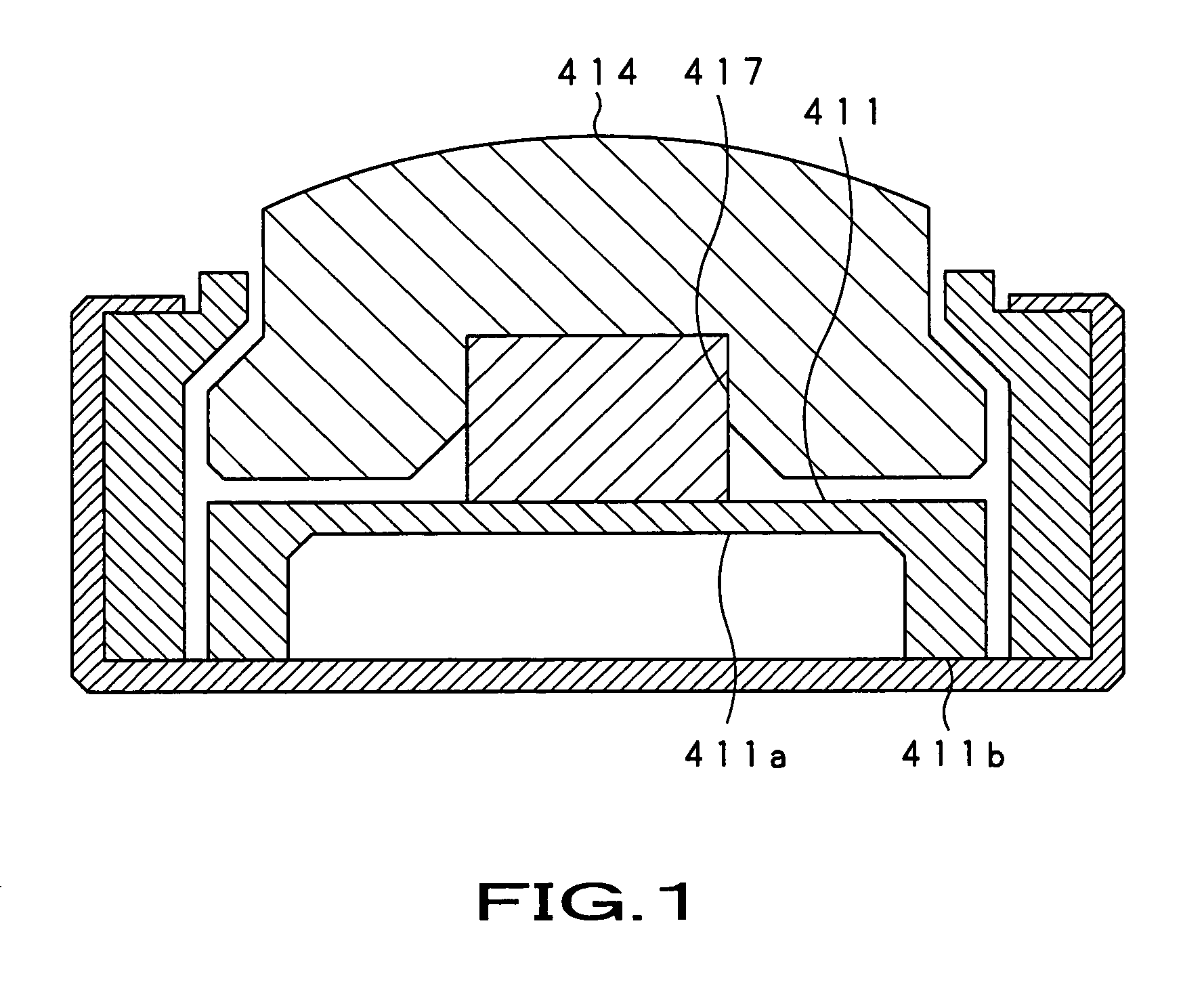
In case the ZMP detecting sensors (load sensor) are provided as above, however, when the robot apparatus walks on the aforementioned discontinuous walking surfaces, the sole member will bend or be otherwise deformed so that the load sensor will be applied with an extremely large load, thus be deteriorated in accuracy of detection or broken.
Namely, the requirement for the dimensional accuracy makes it extremely difficult to manufacture a robot apparatus using such double-structure feet.
However, use of the above-mentioned load sensor in the foot of a robot apparatus will lead to the following problem.
Namely, the conventional load sensor cannot detect a load with a high accuracy.
Therefore, the pressure-sensitive portion of the diaphragm is applied with a very large load even when the driving member slightly varies in characteristic, which is likely to cause the diaphragm to be broken in some cases.
With the rubber-made driving member, however, it is extremely difficult to detect a load stably even with a large variation of the environmental condition.

Method used


Image

  • Robot apparatus and load sensor
  • Robot apparatus and load sensor
  • Robot apparatus and load sensor

Examples


Embodiment Construction

[0050]The present invention will be described in detail concerning the embodiments thereof with reference to the accompanying drawings. The following description will cover first the load sensor according to the present invention, and then the legged robot apparatus having feet each having the load sensor provided therein.

[0051]FIG. 2 is a longitudinal-sectional view of the load sensor, generally indicated with a reference 10, according to the present invention, and FIG. 3 is a plan view of a diaphragm 11 as the pressure detecting means used in the load sensor 10 according to the present invention. According to the present invention, the diaphragm 11 included in the load sensor 10 has a central portion thereof formed thin as a pressure-sensitive portion 11a. The pressure-sensitive portion 11a has four strain gauges provided thereon, and there is mounted a driving member 17 on the upper surface of the pressure-sensitive portion 11a, coupled to an activating member 14 via an elastic m...


PUM


Abstract

A load sensor that is inoperable even when applied with a large load, has a simple structure easily designed to be lightweight and compact and can detect a load with a high accuracy, and a legged robot apparatus including the load sensor in each of legs thereof. The robot apparatus includes the load sensors counting more than one and each of which detects, as an external force, a reaction applied when the leg abuts a ground surface. The load sensor includes a diaphragm, an activating member that is applied with an external force, a driving member forming along with the activating member a double structure and which presses the pressure-sensitive portion, and an elastic member.

Description

BACKGROUND OF THE INVENTION[0001]1. Title of the Invention[0002]The present invention relates to a load sensor that detects a load in response to an applied pressure ranging up to a predetermined load, and a robot apparatus having the load sensor provided at each of leg portions thereof, for example.[0003]This application claims the priority of the Japanese Patent Application No. 2003-070721 filed on Mar. 14, 2003 and No. 2003-067769 filed on Mar. 13, 2003, the entirety of which is incorporated by reference herein.[0004]2. Description of the Related Art[0005]Recently, the research and development on legged robot apparatuses modeled on bipedal animals walking in erect posture such as the human being, monkey or the like have made remarkable advance, and the demand for practical applications of such robot apparatuses has become larger and larger. In the meantime, the bipedal robot apparatuses walking in erect posture are not so stable as a crawler-, quadruped- and hexapod-type ones and...

Claims


Application Information

Patent Timeline
IPC IPC(8): G05B13/00B25J13/08G01L1/22G01L1/26
CPCB25J13/085G01L1/2231G01L1/26
Inventor MIURA, AKITOMAEDA, RYOICHITOSAKA, SUSUMUIGARASHI, TAKESHIKOIKE, GOUSHI
Owner SONY CORP
Learn More