
Light transmission and reception module, sub-mount, and method of manufacturing the sub-mount

a light transmission and reception module technology, applied in the field of light transmission and reception modules, can solve the problems of high cost of photolithography, (4) the accuracy of the obtained core diameter is not good, and achieves the effects of low cost, easy and reliable mounting, and excellent mass production

Inactive Publication Date: 2008-03-11
FUJIFILM BUSINESS INNOVATION CORP
View PDF39 Cites 35 Cited by
  • Summary
  • Abstract
  • Description
  • Claims
  • Application Information

AI Technical Summary

Benefits of technology

[0021]The invention also presents a method of manufacturing a sub-mount capable of mass-producing precise sub-mounts at low cost.
[0022]The invention further presents an inexpensive and precise sub-mount excellent in mass producibility.
[0023]The invention moreover presents a light transmission and reception module of excellent mass producibility and low cost, capable of mounting easily and reliably, by using an inexpensive and precise sub-mount excellent in mass producibility.
[0031]In the method of manufacturing a sub-mount according to this aspect, since the mold is filled with a curing material and the applied curing material is cured to copy a sub-mount, the sub-mount can be mass-produced at low cost. Besides, since the mold has projection and recess patterns formed thereon for copying the surface configuration of the sub-mount, a precise sub-mount can be copied with high accuracy.
[0033]The sub-mount obtained in this method is excellent in mass production, inexpensive, and precise. Additionally, the light transmission and reception module manufactured by using this sub-mount can be mounted easily and reliably, and is excellent in mass production and lost in cost.
[0035]Also according to the invention, precise sub-mounts can be mass-produced at low cost. That is, the sub-mount of the invention is excellent in mass producibility, inexpensive, and precise, and the light transmission and reception module of the invention can be mounted easily and reliably, and is excellent in mass producibility and low in cost.

Problems solved by technology

However, in the selective polymerization method (1), there are problems in adhesion of the film.
In the methods (2) and (3), the cost is high because of photolithography.
The method of (4) has problems in precision of the obtained core diameter.
Excellent and practical methods from the viewpoint of performance are the methods (2) and (3) only, but they are costly.
Further, any one of the methods (1) to (5) is not applicable to formation of macromolecular optical waveguide in a wide and flexible plastic substrate.
On the other hand, a flat optical fiber tape bundling several strands of resin-coated optical fibers is used in optical wiring, but the optical fiber is made of quartz glass tube and is not resistant to bending and folding, and the degree of freedom of wiring is also small.
In addition to these problems, in the methods of manufacturing a macromolecular optical waveguide proposed so far, it is required to bury a mirror in order to form a 90-degree folding mirror, or positioning at high precision is required in the case of adhering a waveguide and light emitting and detecting elements, whereby the mounting cost is high.
For the precise processing of such sub-mount, however, each submount must be processed by fine processing technology such as reactive ion etching (RIE), and the manufacturing cost of the sub-mount becomes very high.

Method used


Image

  • Light transmission and reception module, sub-mount, and method of manufacturing the sub-mount
  • Light transmission and reception module, sub-mount, and method of manufacturing the sub-mount
  • Light transmission and reception module, sub-mount, and method of manufacturing the sub-mount

Examples


first embodiment

[0063]With referring to the drawings, a first embodiment of the present invention is specifically described below.

[Light Transmission and Reception Module]

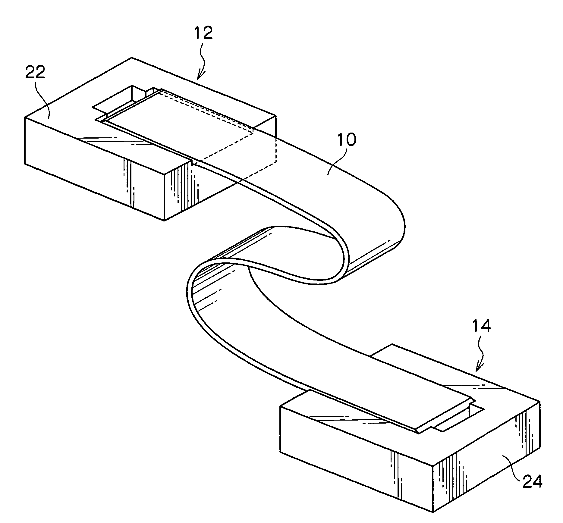
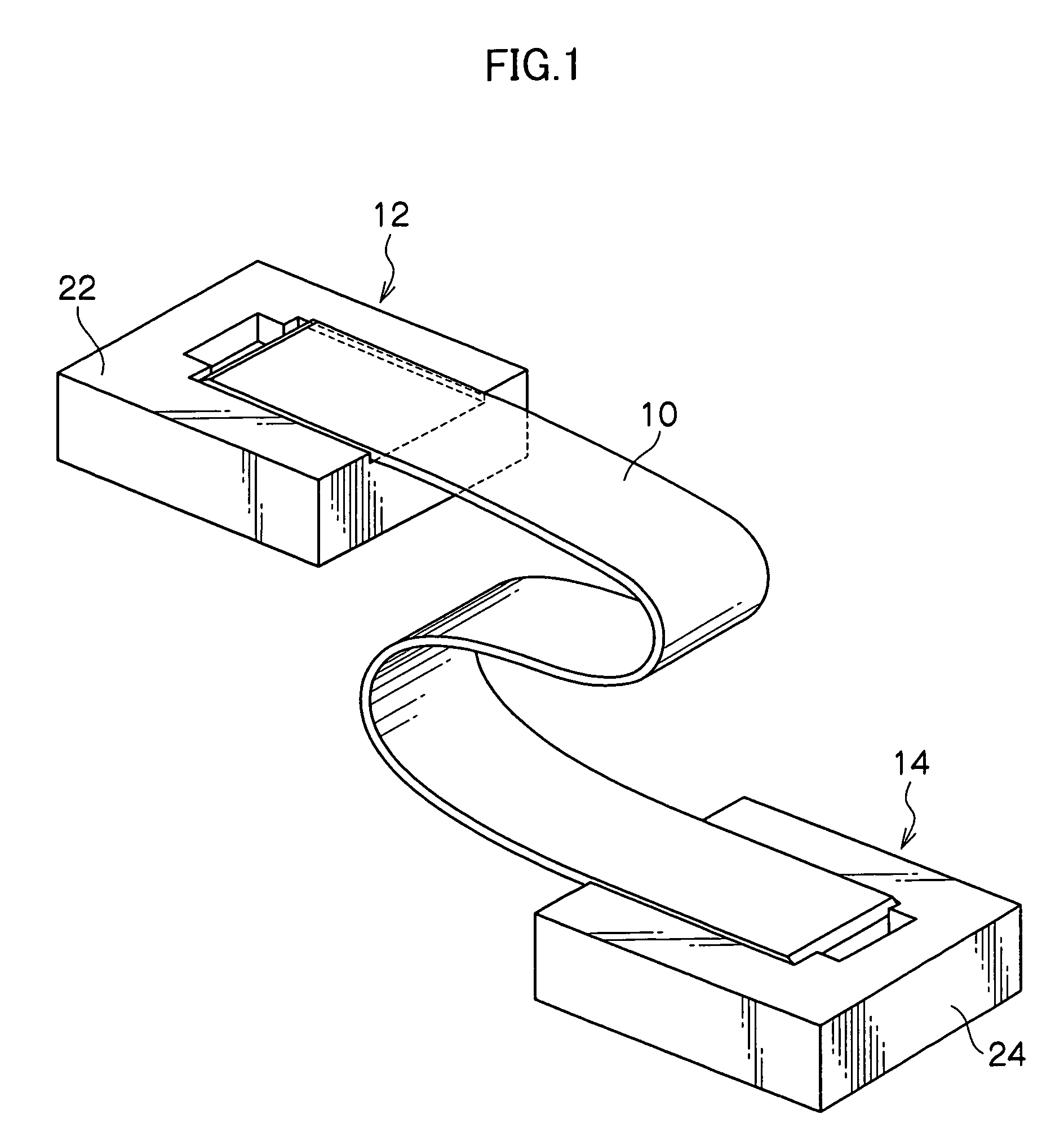
[0064]FIG. 1 is a schematic structural diagram of light transmission and reception module in the first embodiment. This light transmission and reception module is composed of, as shown inFIG. 1, a belt-shaped macromolecular optical waveguide film 10, and optical transmission and reception sections 12, 14 for transmitting and receiving an optical signal through an optical waveguide formed in the macromolecular optical waveguide film 10.

[0065]The optical transmitter 12 has a sub-mount 22, and one end of the macromolecular optical waveguide film 10 is held on the sub-mount. The optical transmission and reception section 14 has a sub-mount 24, and other end of the macromolecular optical waveguide film 10 is held on the sub-mount 24.

[0066]The macromolecular optical waveguide film 10 is composed of a flexible transparent resin film, and...

second embodiment

[0181]Referring now to the drawings, a second embodiment of the invention is specifically described below.

[Light Transmission and Reception Module]

[0182]FIG. 9 is a schematic structural diagram of light transmission and reception module in the second embodiment. This light transmission and reception module is composed of, as shown in FIG. 9, a belt-shaped macromolecular optical waveguide film 210, and optical transmission and reception sections 212, 214 for transmitting and receiving an optical signal through an optical waveguide formed in the macromolecular optical waveguide film 210. The optical transmitter 212 has a surface emission type semiconductor laser diode (LD) 232 as light emitting element, a photo diode (PD) 234 as light detecting element, and a sub-mount 222, and one end of the macromolecular optical waveguide film 210 is held on the sub-mount 222. The optical transmission and reception section 214 has LD 232, PD 234, and sub-mount 224, and other end of the macromolecul...

third embodiment

[0239]Referring now to the drawings, a third embodiment of the invention is specifically described below.

[Manufacturing Method of Sub-Mount]

[0240]A method of manufacturing a sub-mount of the invention comprises (1) a mold production step of producing a mold having projections and recesses for copying the surface configuration of a sub-mount, (2) a filling step of filling the produced mold with curing material, (3) a curing step of curing the applied curing material, and (4) a releasing step of separating a copied sub-mount from the mold.

[0241]A method of producing a mold includes (A) a method of producing a mold by curing liquid silicone rubber on master plate of sub-mount, (B) a method of producing a mold by etching a silicon substrate, and (C) a method of producing a mold by casting a metal. The manufacturing method of the sub-mount using the mold produced in method (A) will be referred to as “the duplication method using silicone resin” hereinafter, and the manufacturing method o...


PUM


Abstract

A light transmission and reception module includes: a belt-shaped macromolecular optical waveguide film having an optical waveguide, an optical transmitter having a light emitting element and a first sub-mount for holding the light emitting element, for holding one end of the macromolecular optical waveguide film on the first sub-mount so that a light emitted from the light emitting element may be coupled to an incident end surface of the optical waveguide, and an optical receiver having a light detecting element and a second sub-mount for holding the light detecting element, for holding the other end of the macromolecular optical waveguide film on the second sub-mount so that the light emitted from an exit end surface of the optical waveguide may be received in the light detecting element.

Description

CROSS-REFERENCE TO RELATED APPLICATION[0001]This application claims priority under 35 USC 119 from Japanese Patent Applications Nos. 2005-60438, 2005-80191 and 2005-84914, the disclosures of which are incorporated by reference herein.BACKGROUND OF THE INVENTION[0002]1. Field of the Invention[0003]The present invention relates to a light transmission and reception module, and more particularly to a light transmission and reception module for transmitting and receiving an optical signal by way of an optical waveguide formed on a macromolecular optical waveguide film. The invention also relates to a sub-mount used in this light transmission and reception module, and a method of manufacturing the same sub-mount.[0004]2. Description of the Related Art[0005]Hitherto, various methods of manufacturing a macromolecular optical waveguide have been proposed, including (1) a method of impregnating a film with a monomer, exposing the core selectively to change the refractive index thereof, and e...

Claims


Application Information

Patent Timeline
Patent Type & Authority Patents(United States)
IPC IPC(8): G02B6/12
CPCG02B6/02042G02B6/10G02B6/138G02B6/4214G02B6/4246G02B6/43G02B6/02033G02B6/423
Inventor OHTSU, SHIGEMISHIMIZU, KEISHIYATSUDA, KAZUTOSHIAKUTSU, EIICHI
Owner FUJIFILM BUSINESS INNOVATION CORP
Learn More