
Electrical signal transmission connector assembly with magnetically connected receptacle and plug

a technology of electrical signals and connectors, which is applied in the direction of telephony connectors, electrical devices, coupling device connections, etc., can solve the problems of increasing the weight of cables, and affecting the service life of cables

Inactive Publication Date: 2008-03-11
KOH CHAO MING
View PDF4 Cites 66 Cited by
  • Summary
  • Abstract
  • Description
  • Claims
  • Application Information

AI Technical Summary

Benefits of technology

[0007]A primary object of the present invention is to provide an electric signal transmission connector assembly that includes a receptacle and at least one plug, which are internally provided with a permanent magnet each, so as to connect to one another through magnetic attraction without the problems of damaged plug or receptacle connected via mechanical structures.
[0009]A further object of the present invention is to provide an electric signal transmission connector assembly that includes a receptacle and at least one plug, which are magnetically connected to one another and include a metal cover each to protect internal magnets against collision and reduce internal and external electromagnetic interference, so as to prevent high-frequency signals from overflowing or leaking.

Problems solved by technology

With these conventional mechanical connecting structures, the plug and the receptacle tend to become damaged and the blade on the plug tends to break when the plug has been plugged or unplugged for many times or at incorrect angular position, or been unintentionally pulled.
However, this way will inevitably increase the weight of cable and form waste of material.
However, only one single magnet-containing connector can be mated with one contact of the electrode.
There is not structure allowing multiple pieces of the magnet-containing connectors to be stacked up and connected to one contact member at the same time.
However, these prior do not take electromagnetic shielding of high-frequency signal into consideration, and the plugs thereof could not be stacked up for connecting to the same one receptacle.

Method used


Image

  • Electrical signal transmission connector assembly with magnetically connected receptacle and plug
  • Electrical signal transmission connector assembly with magnetically connected receptacle and plug
  • Electrical signal transmission connector assembly with magnetically connected receptacle and plug

Examples


Embodiment Construction

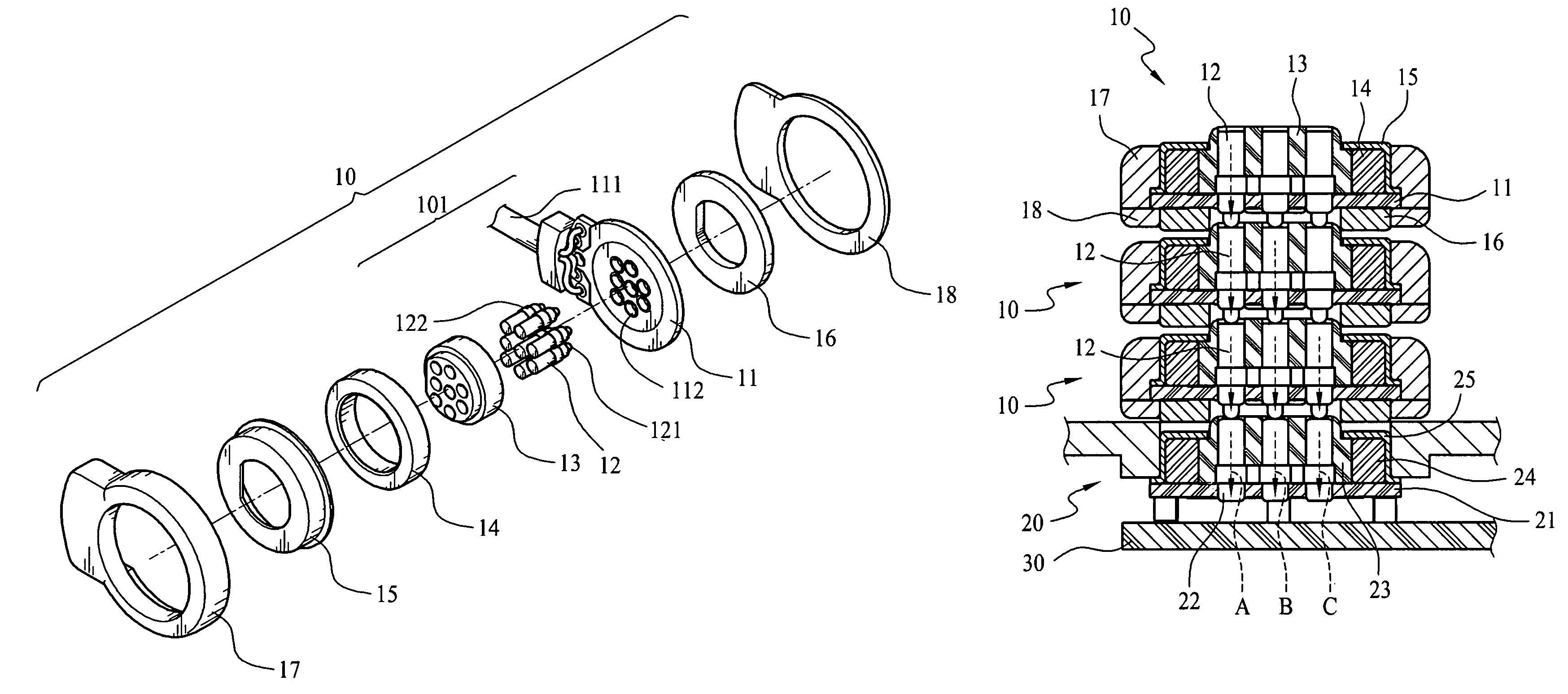
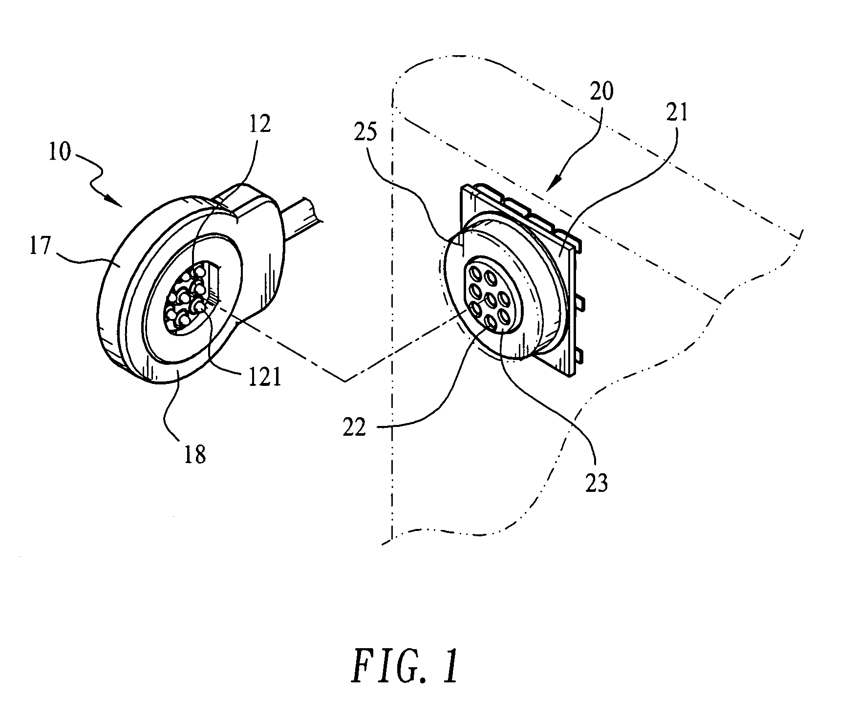
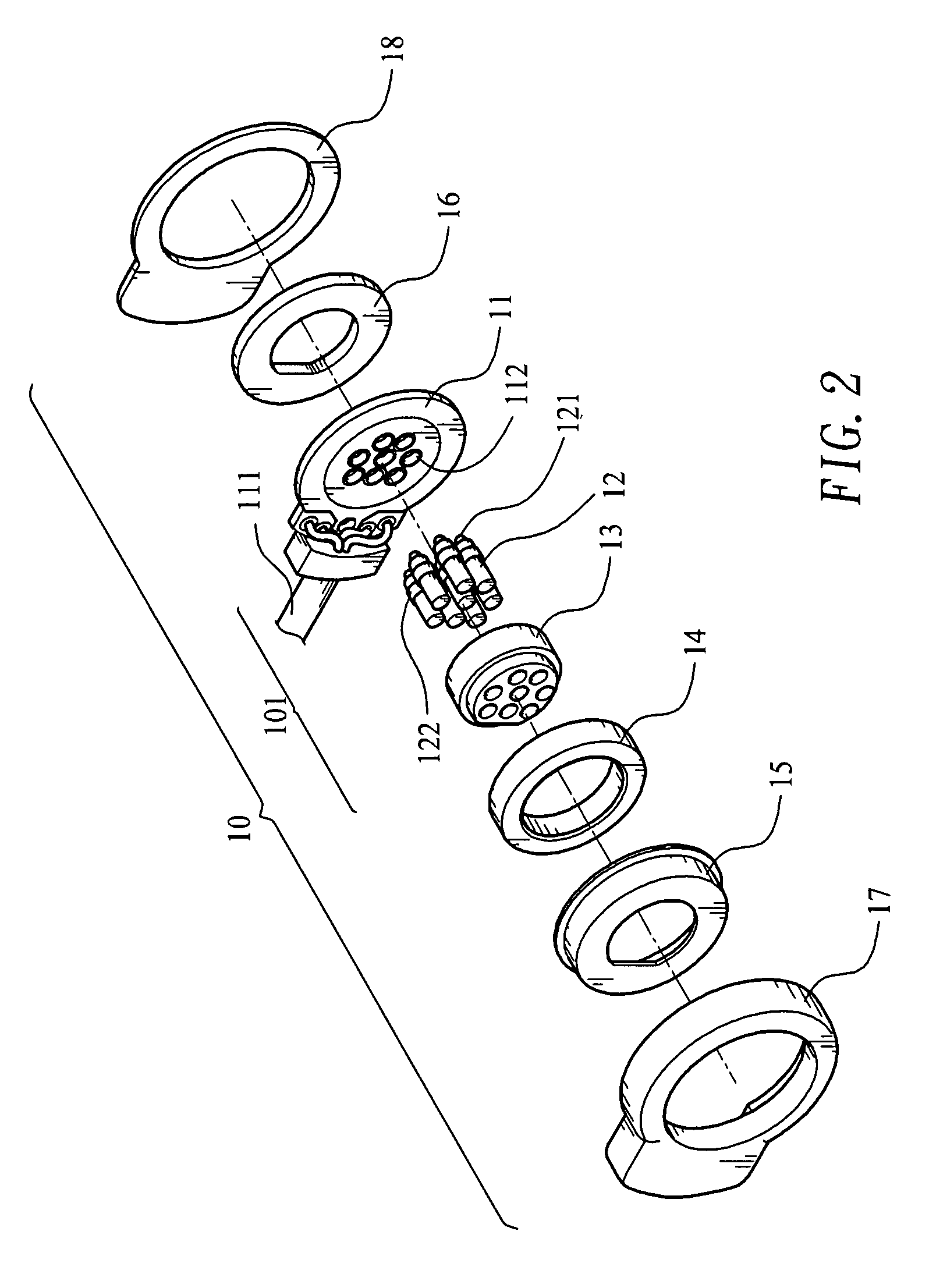
[0033]Please refer to FIG. 1 that is a perspective view of a connector assembly according to an embodiment of the present invention. As shown, the connector assembly of FIG. 1 includes a plug 10 and a receptacle 20 that are magnetically connected to each other for transmitting electric signals. Please also refer to FIGS. 2 and 3 that are exploded perspective views of the plug 10 and the receptacle 20, respectively. As can be seen from FIGS. 2 and 3, the plug 10 and the receptacle 20 internally include a permanent magnet 14 and 24, respectively, so that the plug 10 can be magnetically connected to the receptacle 20 to enable transmission of electric signals and supply of power via the connector assembly of the present invention.

[0034]FIG. 4 is a sectioned side view showing the plug 10 and the receptacle 20 before being magnetically connected to each other. Please refer to FIGS. 2 and 4 at the same time. The plug 10 includes an upper and a lower case 17, 18 that together define an int...


PUM


Abstract

An electric signal transmission connector assembly includes at least one plug and a receptacle mounted to an electronic apparatus. The plug and the receptacle are internally provided at two opposite positions with a permanent magnet each, so that the plug may be easily connected to the receptacle through magnetic attraction between the two magnets. The plug and the receptacle also include a plurality of terminals each. When the plug and the receptacle are magnetically connected to each other, the terminals thereof are contacted with one another to enable transmission of electric signals or supply of power via the plug and the receptacle. Two or more plugs may be stacked up to magnetically connect to the same one receptacle to save a lot of space by magnetically connecting a lower connecting section of an upper plug to an upper receiving section of a lower plug.

Description

FIELD OF THE INVENTION[0001]The present invention relates to an electric signal transmission connector assembly, and more particularly to a connector assembly including a receptacle and at least one stackable plug, which are internally provided with a magnet each, so as to magnetically connect to one another.BACKGROUND OF THE INVENTION[0002]With the advanced technologies, there are developed more and more types of electronic products, which are able to integrate multiple different functions. For this purpose, there are multiple electric connector assemblies provided on the modern electronic products for connecting to other electronic product for transferring data between them.[0003]A connector assembly on general electronic products, such as earphones, USB devices, power supply, etc., usually includes a male connector or plug that has a projected blade as long as 1 cm to 2 cm for plugging in a female connector or receptacle. The projected blade is held to the receptacle by frictiona...

Claims


Application Information

Patent Timeline
IPC IPC(8): H01R13/60
CPCH01R13/2421H01R33/7671H01R2201/16Y10S439/923
Inventor KOH, CHAO MING
Owner KOH CHAO MING
Learn More