Insulator and manufacturing method thereof, and stator for electric rotating machine
a manufacturing method and stator technology, applied in the direction of magnets, magnetic circuit shapes/forms/construction, magnetic bodies, etc., can solve the problems of complicated core segment handling, and difficult stator manufacturing process, so as to facilitate the manufacture of a stator
- Summary
- Abstract
- Description
- Claims
- Application Information
AI Technical Summary
Benefits of technology
Problems solved by technology
Method used
Image
Examples
first embodiment
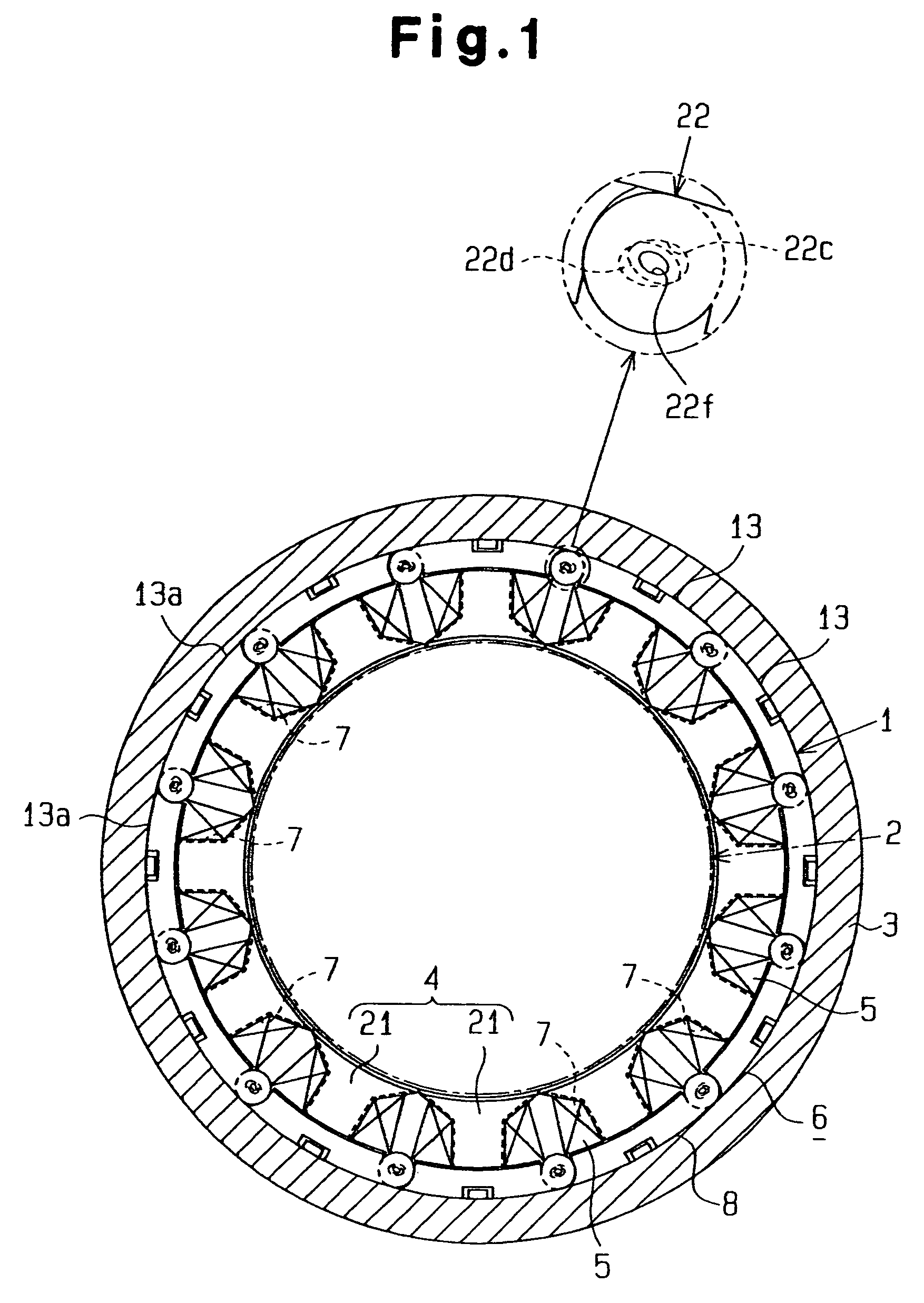
[0054]the present invention will now be described with reference to FIGS. 1 to 12. As shown in FIG. 1, an electric rotating machine, which is a brushless motor in this embodiment, includes a stator 1 and a rotor 2 (indicated with a dashed line in FIG. 1). The rotor 2 has magnets (not shown) located opposite to the stator 1. The stator 1 is located in a substantially cylindrical housing 3 and surrounds the rotor 2. The stator 1 includes a stator core 6, an insulator 4, and coils 5.
[0055]The stator core 6 includes an annular portion 8 and teeth 7, which extend from the annular portion 8 radially toward the axis of the annular portion 8. Each coil 5 is wound around one of the teeth 7. In the first embodiment, twelve teeth 7 are arranged at equal angular intervals of 30 degrees.
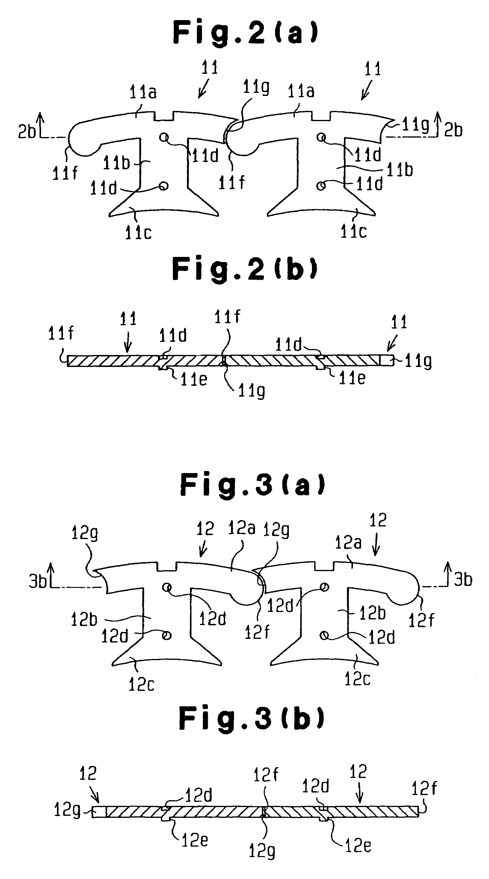
[0056]As shown in FIGS. 4(b) and 4(c), the stator core 6 is formed by core segments (divided core members) 13 arranged in an annular form. Each core segment 13 is formed by alternately laminating first piece memb...
second embodiment
[0090]the present invention will now be described with reference to FIGS. 13 to 16.
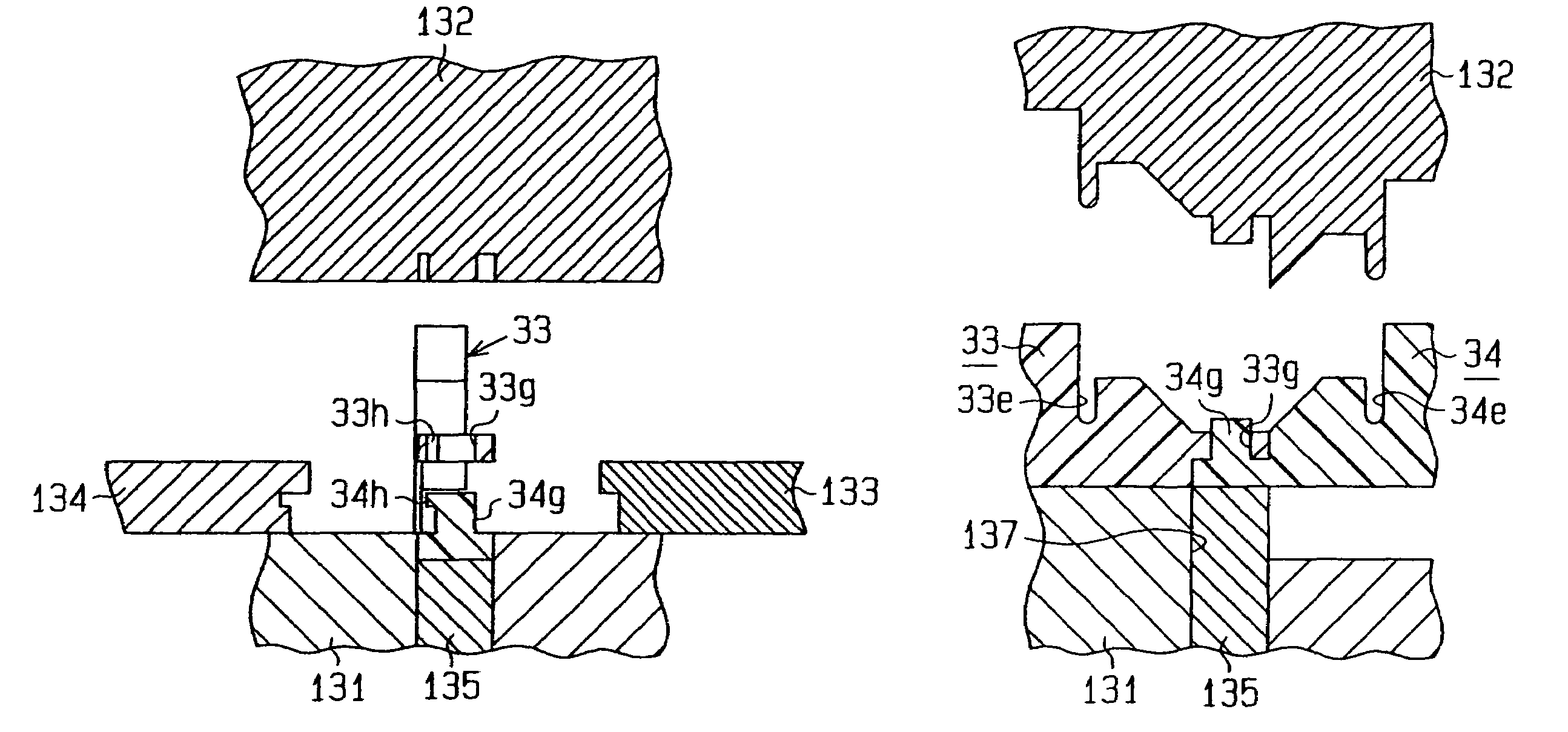
[0091]The insulator 4 shown in FIG. 5 is formed by several identical insulating members 21, which are coupled to one another. In the second embodiment, the insulator 4 is formed by alternately arranging two types of insulating members as shown in FIGS. 13 to 16. That is, the insulator 4 is formed by first insulating members 33 (see FIG. 13) and second insulating members 34 (see FIG. 15), which are coupled to one another.
[0092]More specifically, the first and second insulating members 33, 34 are formed of insulative resin material. As the insulating member 21 shown in FIG. 5, each insulating member 33 or 34 includes an arcuate cover 33a or 45a, an inner circumferential cover 33b or 34b, a flat cover 33c or 34c, and a pair of side covers 33d or 34d. Each arcuate cover 33a or 34a has a restricting wall for preventing the coil 5 wound around the corresponding tooth 7 from protruding radially outward. The ...
third embodiment
[0097]the present invention will now be described with reference to FIGS. 17 to 32.
[0098]In the third embodiment, the first and second insulating members 33, 34 of the second embodiment illustrated in FIGS. 13 to 16 are slightly modified. As shown in FIGS. 17 and 18, a notch 33h is formed in each coupling bore 33g of the first insulating member 33 according to the third embodiment. The notch 33h, extends in the radial direction. The pair of notches 33h of each first insulating member 33 extends in directions to separate from each other toward the lower side, that is, toward the inner restricting wall 33f as shown in FIG. 18.
[0099]As shown in FIGS. 19 and 20, a hook 34h is formed at the distal end of each coupling projection 34g of the second insulating member 34. The shape of the hooks 34h matches the shape of the notches 33h. The hooks 34h permit the coupling projections 34g to be inserted into the coupling bores 33g when the first insulating member 33 and the second insulating mem...
PUM
 Abstract
Description
Claims
Application Information
 - R&D
- Intellectual Property
- Life Sciences
- Materials
- Tech Scout
- Unparalleled Data Quality
- Higher Quality Content
- 60% Fewer Hallucinations
Browse by: Latest US Patents, China's latest patents, Technical Efficacy Thesaurus, Application Domain, Technology Topic, Popular Technical Reports.
© 2025 PatSnap. All rights reserved.Legal|Privacy policy|Modern Slavery Act Transparency Statement|Sitemap|About US| Contact US: help@patsnap.com


