
Digitally controlled oscillator

Active Publication Date: 2008-02-26
QORVO US INC
View PDF20 Cites 93 Cited by
  • Summary
  • Abstract
  • Description
  • Claims
  • Application Information

AI Technical Summary

Benefits of technology

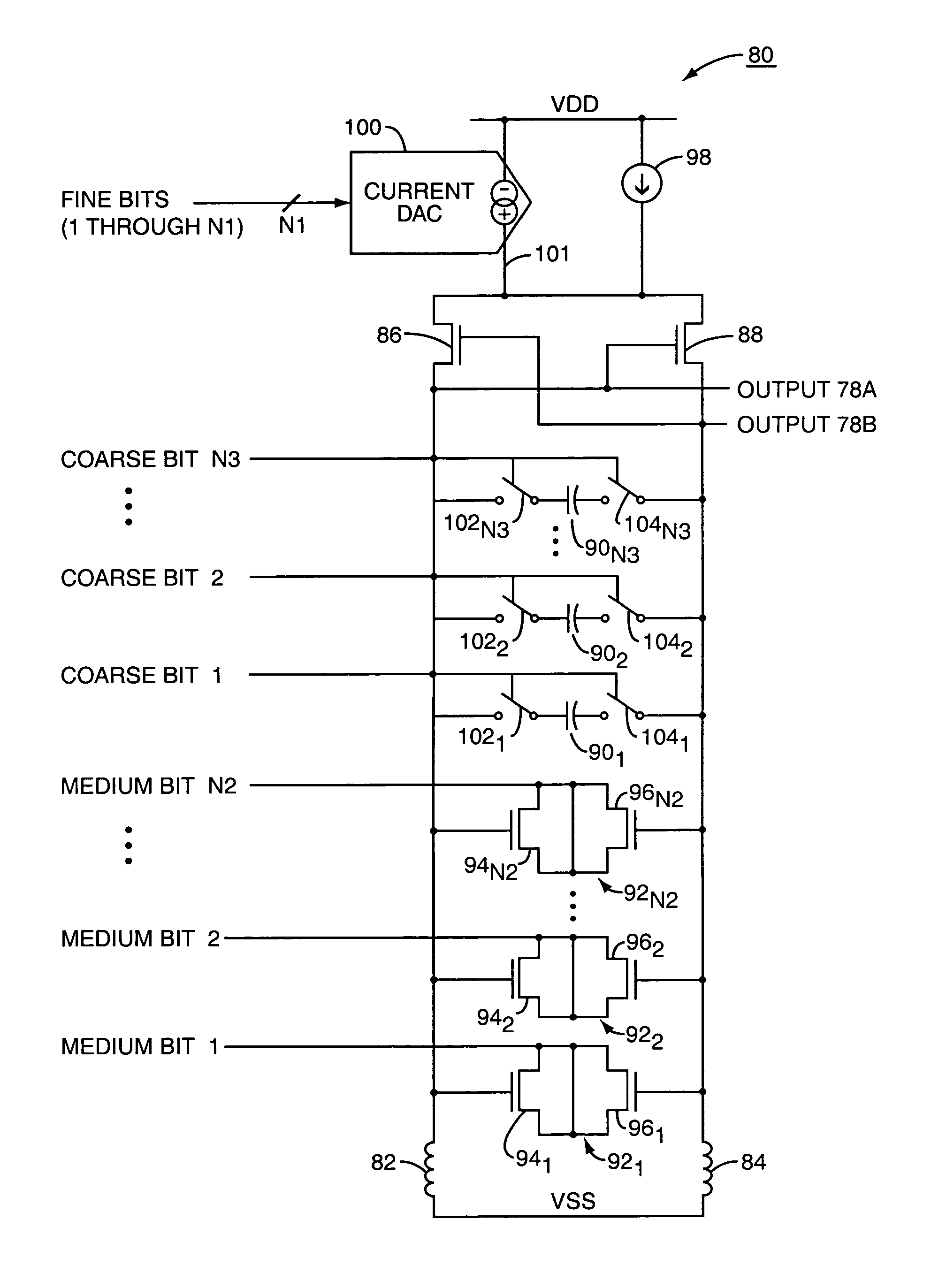
[0007]In a first embodiment, the oscillator is an LC oscillator. This first embodiment has multiple aspects. In a first aspect, the parameter is the capacitance. The component comprises a bank of capacitors that may be switched in or out to vary the capacitance. The digital word controls switches which connect or disconnect capacitors from the circuit, and thereby helps create the desired frequency. In a second aspect, the parameter is still capacitance. The component is a bank of varactors which remain connected but are switched into high or low capacitance states to vary the capacitance. The digital word raises or lowers the capacitance, and thereby helps create the desired frequency. In a third aspect, the parameter is a bias current for the oscillator. The component is a digital to analog converter (DAC) that controls the bias current. The digital word raises or lowers the bias current, and thereby helps create the desired frequency.
[0008]In a second embodiment, the oscillator is a ring oscillator. Like the first embodiment, this second embodiment has multiple aspects corresponding to different parameters which may be controlled. In a first aspect, the parameter is the bias current. The component is a current DAC that controls the bias current provided to the inverters of the ring oscillator. The digital word raises or lowers the current, and thereby helps create the desired frequency. In a second aspect, the parameter is capacitance and the component comprises one or more banks of capacitors that may be connected or disconnected to vary the capacitance. The digital word controls the switches that connect and disconnect the individual capacitors from the circuit, and thereby helps create the desired frequency.

Problems solved by technology

However, these analog varactors alone do not achieve the tuning ranges required for most transceiver systems.
However, this supplemental bank of capacitors requires a state machine to run a coarse tuning algorithm.
Further, as integrated circuit geometries and supply voltages shrink, especially in mobile terminal environments, the analog voltage over which the frequency synthesizer operates also shrinks, requiring complicated architectural changes.

Method used


Image

  • Digitally controlled oscillator
  • Digitally controlled oscillator
  • Digitally controlled oscillator

Examples


Embodiment Construction

[0019]The embodiments set forth below represent the necessary information to enable those skilled in the art to practice the invention and illustrate the best mode of practicing the invention. Upon reading the following description in light of the accompanying drawing figures, those skilled in the art will understand the concepts of the invention and will recognize applications of these concepts not particularly addressed herein. It should be understood that these concepts and applications fall within the scope of the disclosure and the accompanying claims.

[0020]The present invention is directed to a digitally controlled oscillator such as may be used in a mobile terminal. The oscillator includes one or more elements which allow coarse and / or fining tuning of an output frequency of the oscillator. Each of the elements receives a corresponding digital word that in turn affects a parameter of the oscillator to control the output frequency. Particularly contemplated parameters include ...


PUM


Abstract

A tunable oscillator suitable for use in a frequency synthesizer of a transceiver is controlled by varying one or more parameters associated with the oscillator. In particular, a digital control signal affects one or more of the capacitances of the oscillator, the bias voltage of the oscillator, the supply voltage, or the bias current of the oscillator. Changes to one or more of these parameters allows the frequency of the oscillator to be controlled as desired.

Description

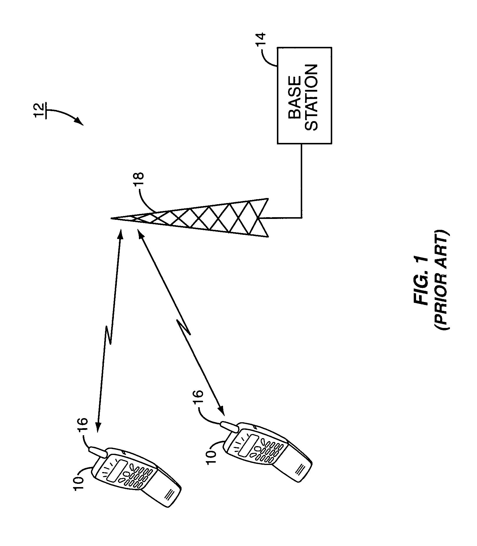
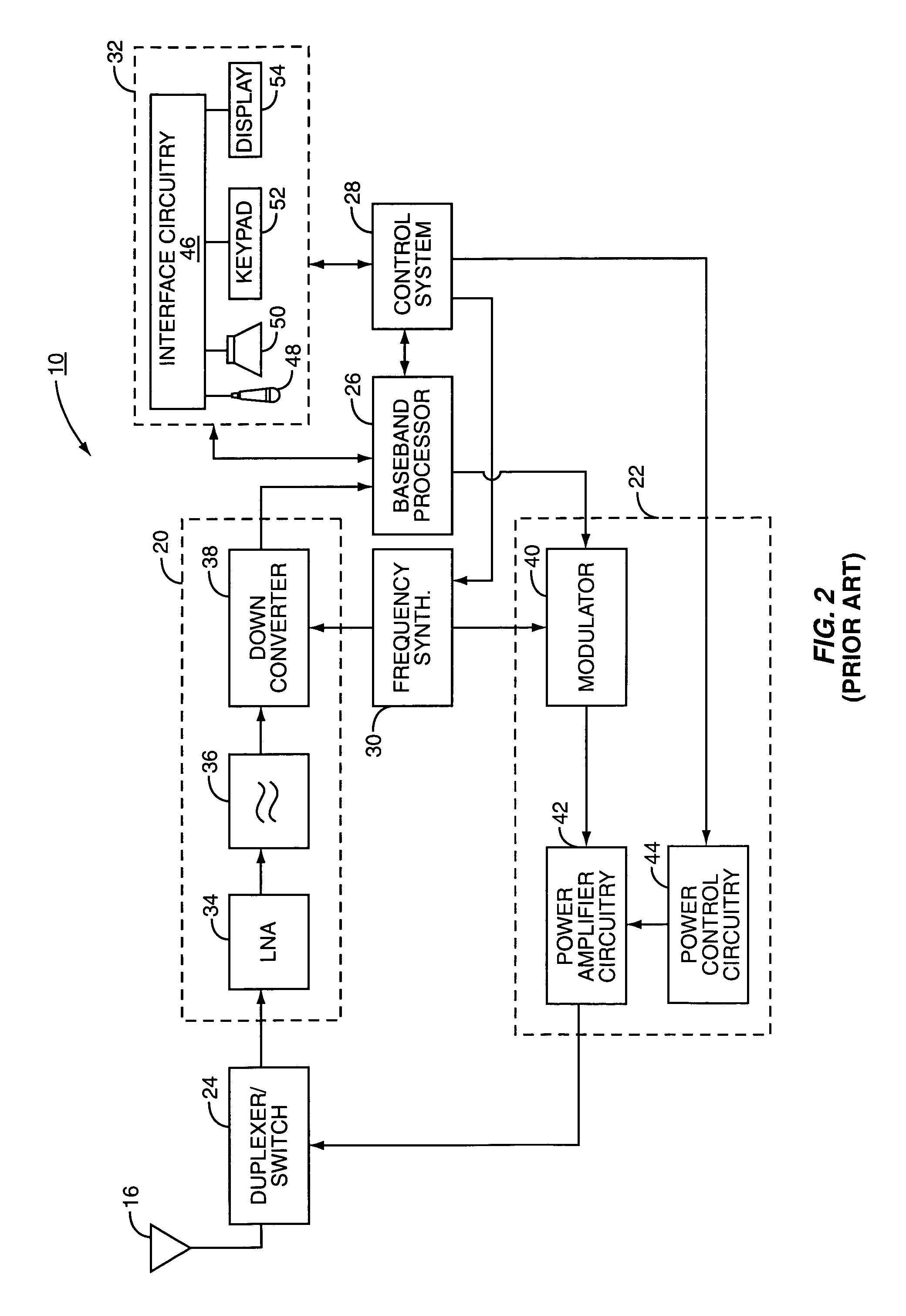
FIELD OF THE INVENTION[0001]The present invention relates to a variable frequency oscillator whose frequency is controlled by a digital signal.BACKGROUND OF THE INVENTION[0002]Wireless transmitters and receivers have become ubiquitous in modern society. While radios and televisions have been commonplace for many years, the explosion of cellular telephones and other mobile terminals has created an overwhelming demand for wireless transceivers. Most such transceivers have a need to switch between frequencies. For example, in a cellular system, the base station may assign the cellular telephone to a particular frequency channel and time slot on which to communicate. The frequency channel lies within the total range of frequencies available for communication within the applicable standard. At a later time, the base station may assign the cellular telephone to a second, different frequency on which to communicate.[0003]To effectuate changing the frequency channel such as when a base stat...

Claims


Application Information

Patent Timeline
IPC IPC(8): H03B5/12H03L7/099
CPCH03L7/0991H03L7/0995H03B5/1228H03L7/0818H03B5/1265H03B5/1253H03B5/1212H03B2200/0074
Inventor JANESCH, STEPHEN T.MARTYNIUK, PAUL G.
Owner QORVO US INC
Learn More