
System and method for treating fuel to increase fuel efficiency in internal combustion engines

a technology for internal combustion engines and fuel efficiency, applied in the field of internal combustion engines, can solve problems such as turbulence or cavitation of fuel, and achieve the effect of increasing fuel efficiency in internal combustion engines

Active Publication Date: 2008-02-26
DONNELLY JOSEPH LOUIS
View PDF11 Cites 53 Cited by
  • Summary
  • Abstract
  • Description
  • Claims
  • Application Information

AI Technical Summary

Benefits of technology

The radial acceleration of fuel results in increased fuel combustion efficiency, altering physical properties such as color, turbidity, and surface tension, leading to improved energy release and efficiency in internal combustion engines.

Problems solved by technology

While in the acceleration chamber, the rotating rotor radially accelerates the fuel and the acceleration, in turn, may generate turbulence or cavitation within the fuel.

Method used


Image

  • System and method for treating fuel to increase fuel efficiency in internal combustion engines
  • System and method for treating fuel to increase fuel efficiency in internal combustion engines
  • System and method for treating fuel to increase fuel efficiency in internal combustion engines

Examples


Embodiment Construction

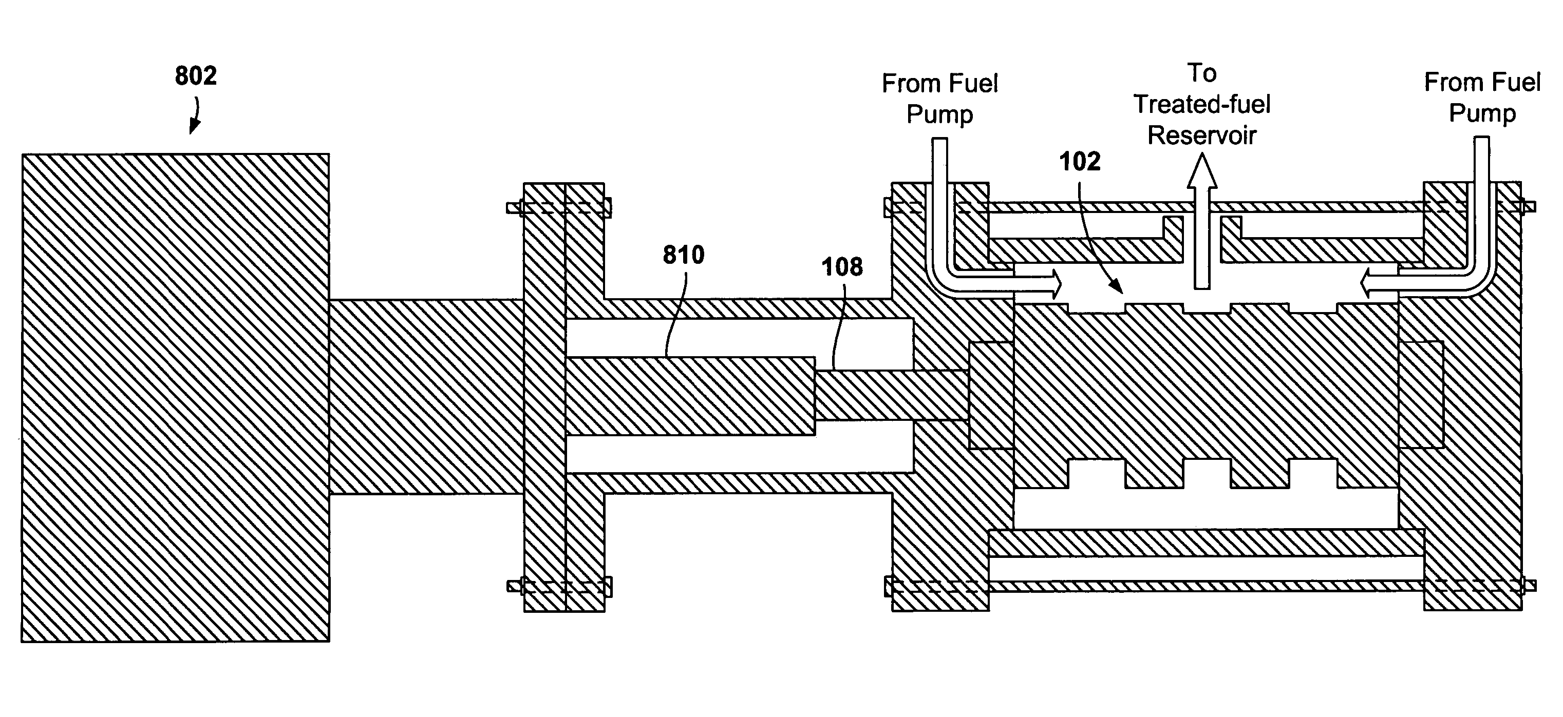
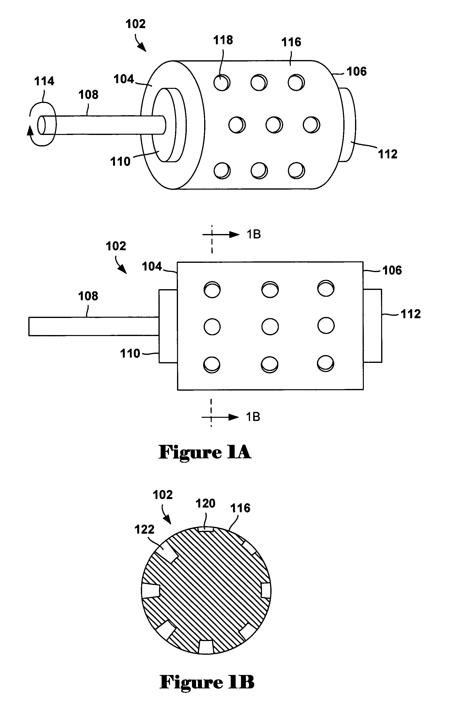
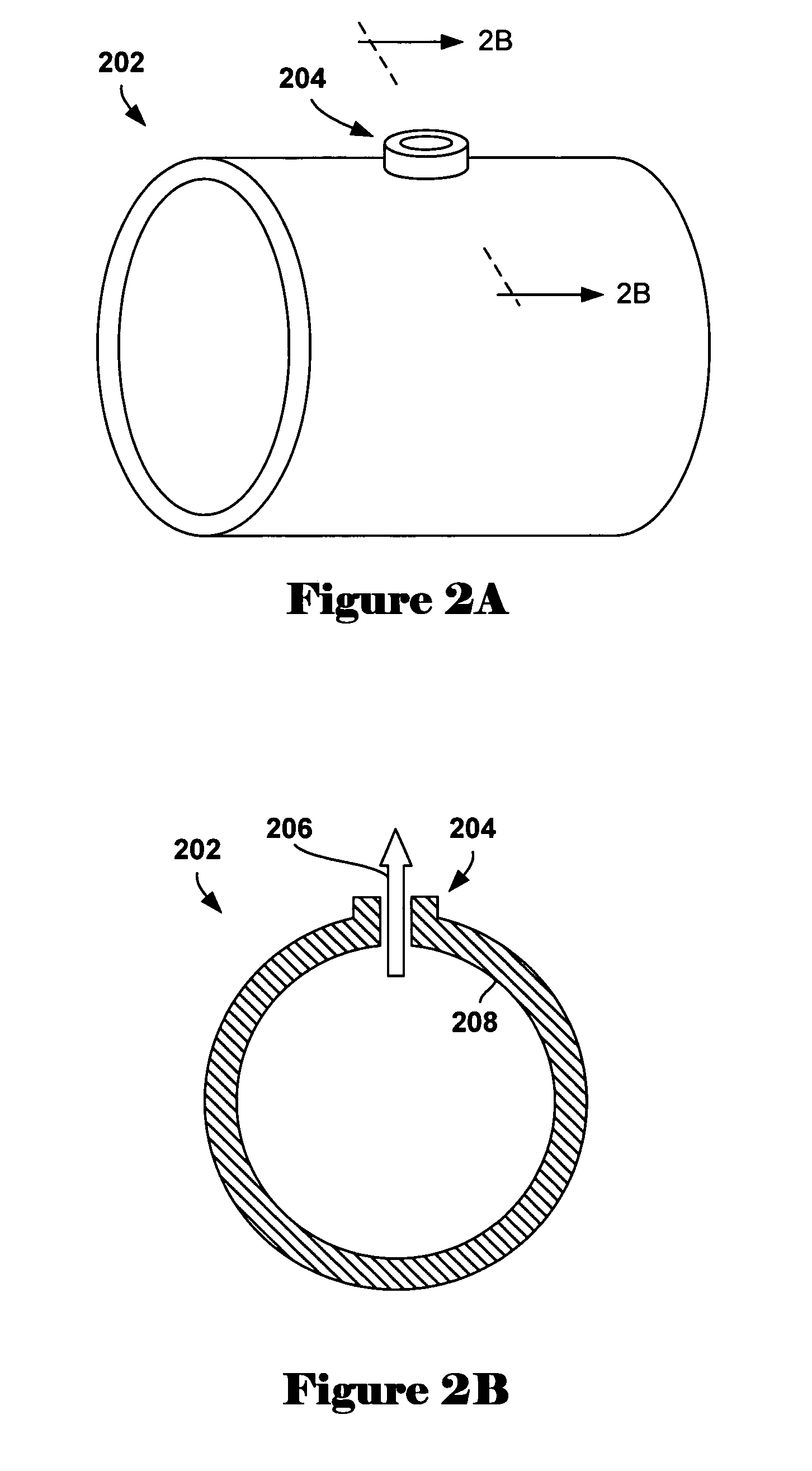
[0024]Various embodiments of the present invention are directed to a system and method to increase fuel efficiency in internal combustion engines by radially accelerating hydrocarbon-based fuel input to a fuel-treatment assembly prior to combustion. In one embodiment of the present invention, fuel is input to a fuel-acceleration chamber within a fuel-treatment assembly. A fuel-treatment assembly includes a rotor, a surrounding rotor housing, and two flanking rotor-housing caps. The fuel-acceleration chamber within the fuel-treatment assembly is a fuel-tight space bounded on the inside by the rotor, on the outside by the rotor housing, and on the sides by the flanking rotor-housing caps. Fuel is input to the fuel-acceleration chamber through intake ports in the rotor-housing caps and radially accelerated by rapid rotation of the rotor. Turbulent flows, and possibly cavitation, are produced by shear forces produced within the fuel. The shear forces result from the extremely large grad...


PUM

PropertyMeasurementUnit
diameteraaaaaaaaaa
diameteraaaaaaaaaa
distanceaaaaaaaaaa

Abstract

Various embodiments of the present invention are directed to a system and method for increasing fuel efficiency in internal combustion engines by radially accelerating fuel prior to combustion. In one embodiment of the present invention, fuel is input, under pressure, to an enclosed fuel-acceleration chamber between a rotating rotor and stationary rotor housing. While in the acceleration chamber, the rotating rotor radially accelerates the fuel and the acceleration, in turn, may generate turbulence or cavitation within the fuel. The fuel is then output from the fuel-acceleration chamber to a treated-fuel reservoir and to a fuel-combustion site.

Description

CROSS-REFERENCE TO RELATED APPLICATION[0001]This application is a continuation-in-part of application Ser. No. 10 / 939,893, filed Sep. 13, 2004, now abandoned.TECHNICAL FIELD[0002]The present invention relates to the field of internal combustion engines, and, in particular, to a system and method for treating fuel to increase fuel efficiency in internal combustion engines.BACKGROUND OF THE INVENTION[0003]Internal combustion engines are a vital part of modern society. Since development of the internal combustion engine, many internal-combustion-engine-based industries, such as the automobile industry, have devoted enormous amounts of money and resources toward research and development of various ways to increase the useful work realized from a given amount of fuel, or fuel efficiency. Designers and manufacturers of internal combustion engines have improved the fuel efficiency of internal combustion engines, and have improved the fuel used in internal combustion engines.[0004]Internal ...

Claims


Application Information

Patent Timeline
Patent Type & Authority Patents(United States)
IPC IPC(8): B01F3/04
CPCB01F3/04531B01F7/00816B01F2003/04872B01F23/233B01F23/237611B01F27/2722
Inventor DONNELLY, JOSEPH LOUIS
Owner DONNELLY JOSEPH LOUIS
Learn More