
Communication using VCSEL laser array

a laser array and communication technology, applied in the direction of electromagnetic transmission, semiconductor lasers, electromagnetic transmission, etc., can solve the problems of limited switching and modulation speed, relatively slow carrier recombination lifetime, and improvement cannot meet the demand for higher speed in the long run, and achieve fast switching output beams and high frequency

Inactive Publication Date: 2008-02-19
NASA
View PDF33 Cites 46 Cited by
  • Summary
  • Abstract
  • Description
  • Claims
  • Application Information

AI Technical Summary

Benefits of technology

The invention is a method for using external modulation of light from a laser to create a high-speed, fast switching output beam for terrestrial and space communications. The method involves using an array of vertical cavity surface emitting lasers (VCSELs) that are spatially coupled together. The lasers are connected to a current source and the output beam is then transferred to two receivers. The resulting far field pattern has two lobes that oscillate out of phase and can be used for beam switching. The invention uses computer simulations to model the behavior of the laser and carrier density. The invention can produce an optical data stream by modulating the amplitude, phase, or frequency of the optical carrier. The invention can be implemented using external modulators such as Mach-Zehnder interferometers or electro-absorption modules. The invention has applications in optical fiber communication networks and can provide high-speed switching for routing and switching between optical beams.

Problems solved by technology

The limits to switching and modulation speed of semiconductor lasers are fundamental bottlenecks for information processing and transmission in optical communication systems.
These limits come from the relatively slow carrier recombination lifetime in the III-V semiconductors used for optical applications.
Though progress in pushing this limit in the past has been made, these improvements cannot meet the demand for higher speed in the long run.
However, full advantage cannot be taken of compact two-dimensional (2D) VCSEL arrays if bulky external passive optical elements are used for routing and switching.

Method used


Image

  • Communication using VCSEL laser array
  • Communication using VCSEL laser array
  • Communication using VCSEL laser array

Examples


Embodiment Construction

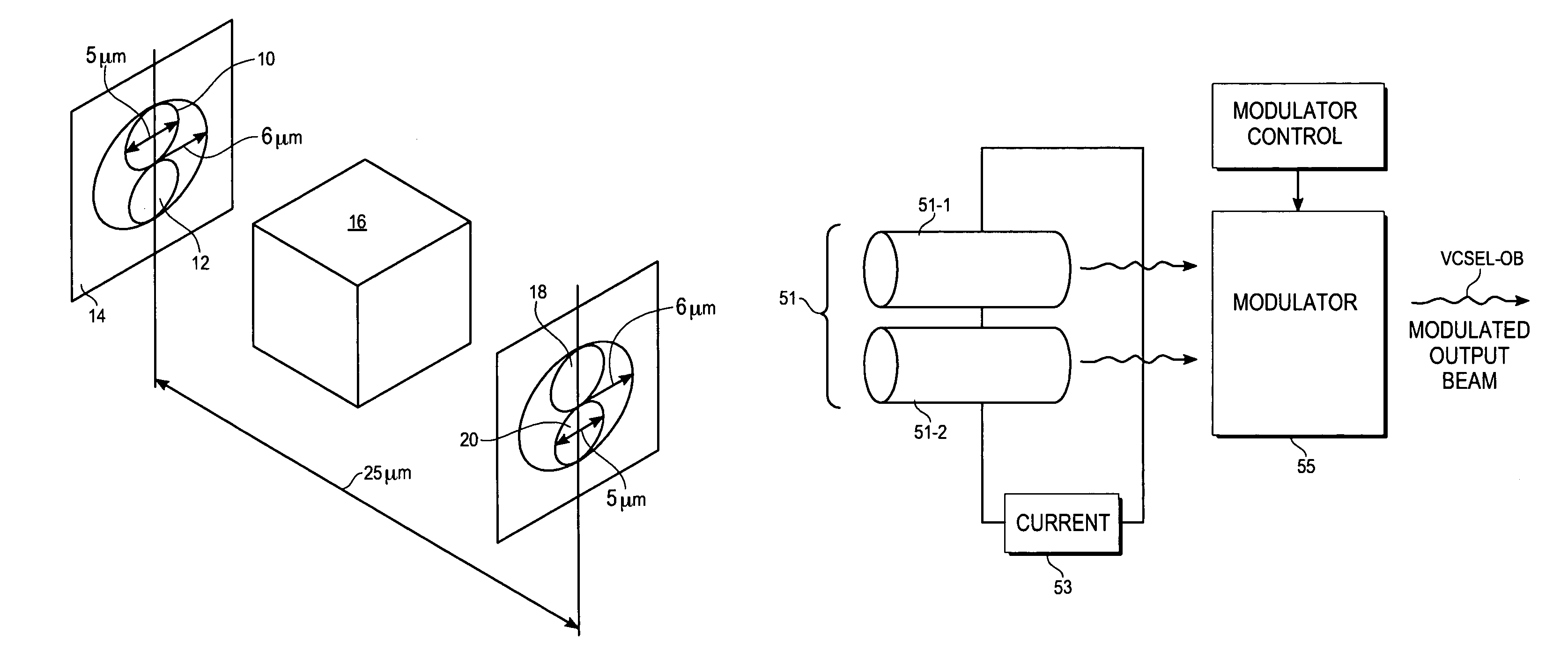
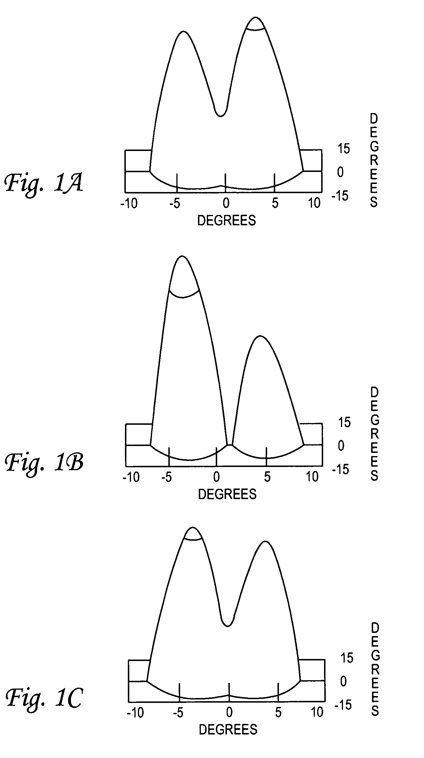
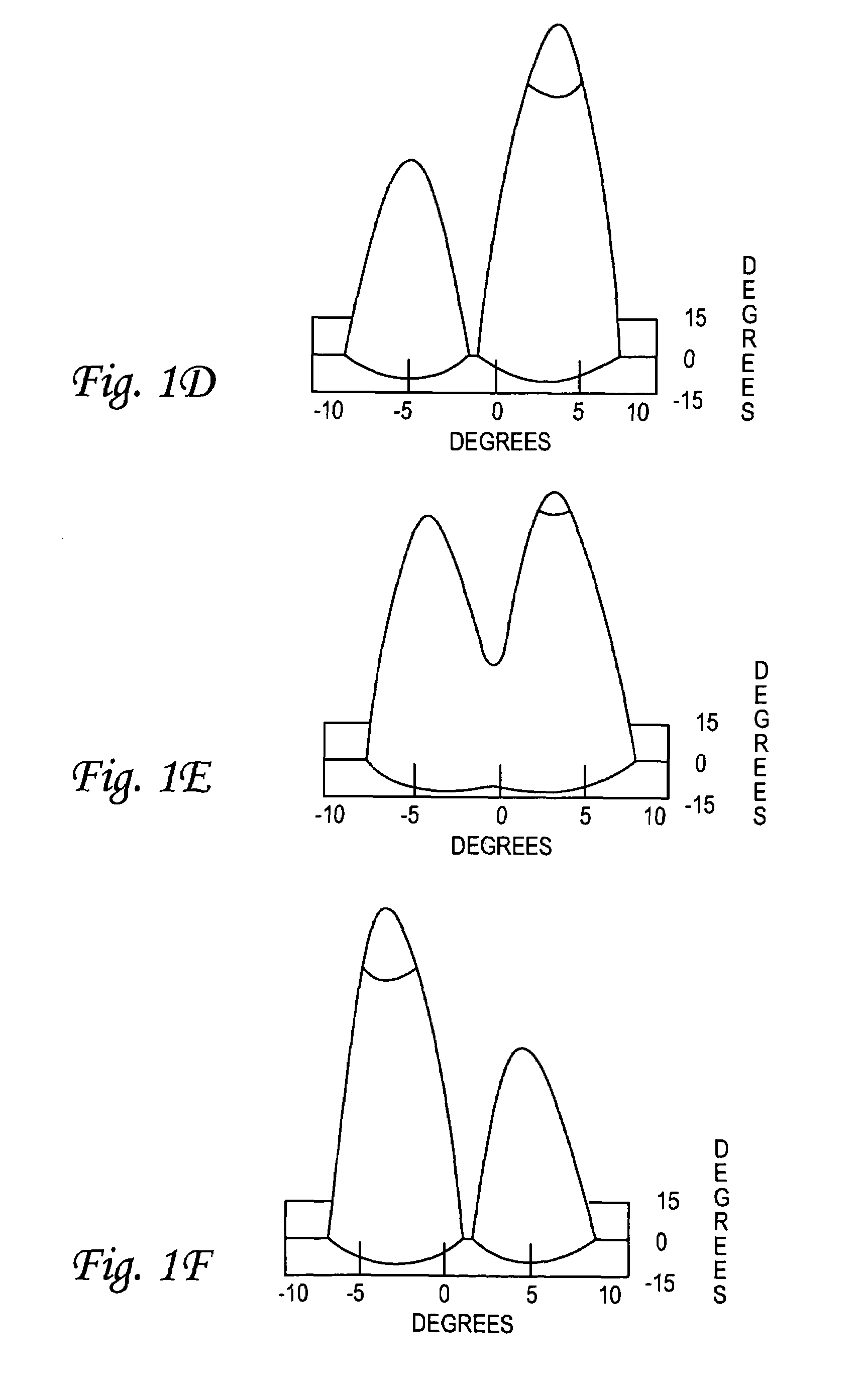
[0026]A method of directional beam switching is disclosed that uses two or more closely coupled vertical cavity surface emitting lasers (VCSELs). When two or more VCSELs are coupled by a small inter-VCSEL separation and are biased at the same steady current near threshold, the resulting light output is spatially oscillating at an extremely high frequency. The invention is based on computer simulations of the light output of coupled VCSELs. The model equations that are solved on the computer are an approximation to the semi-conductor Maxwell-Bloch equations. Simulations have been performed for two coupled VCSELs operating at 980 nm with circular current apertures of 5.6 μm in diameter, and the resulting switching frequency is at 42 GHz. The far field beams are separated by about eight degrees. The near field pattern shows two spots that oscillate in relative intensity. However, these spots oscillate ninety degrees out of phase with respect to the oscillation in the far field pattern....


PUM


Abstract

Ultrafast directional beam switching, using coupled VCSELs is combined with a light modulator to provide information transfer at bit rates of tens of GHz. This approach is demonstrated to achieve beam switching frequencies of 32-50 GHz in some embodiments and directional beam switching with angular differences of about eight degrees. This switching scheme is likely to be useful for ultrafast optical networks at frequencies much higher than achievable with other approaches. A Mach-Zehnder interferometer, a Fabry-Peror etalon, or a semiconductor-based electro-absorption transmission channel, among others, can be used as a light modulator.

Description

CROSS REFERENCE TO RELATED APPLICATIONS[0001]This application is a continuation-in-part of prior application Ser. No. 10 / 171,554, filed Jun. 10, 2002, now U.S. Pat. No. 6,865,208.ORIGIN OF THE INVENTION[0002]The invention described herein was made by an employee of the United States Government and may be manufactured and used by or for the Government for government purposes without the payment of any royalties thereon or therefor.TECHNICAL FIELD OF THE INVENTION[0003]The present invention relates to information transmission using optical communication systems, including a combination of two or more vertical-cavity surface emitting lasers (VCSELs).BACKGROUND OF THE INVENTION[0004]The limits to switching and modulation speed of semiconductor lasers are fundamental bottlenecks for information processing and transmission in optical communication systems. These limits come from the relatively slow carrier recombination lifetime in the III-V semiconductors used for optical applications. T...

Claims


Application Information

Patent Timeline
Patent Type & Authority Patents(United States)
IPC IPC(8): H04B10/00H01S3/00H01S5/00H01S5/062H01S5/42
CPCH01S5/423H01S5/06226H01S5/0624
Inventor GOORJIAN, PETER M.
Owner NASA
Learn More