
Technique for improving Pirani gauge temperature compensation over its full pressure range

a technology of temperature compensation and pirani gauge, which is applied in the direction of fluid pressure measurement, measurement devices, instruments, etc., can solve the problems of ambient temperature-caused errors of pirani gauges shown in figs. 1a and 1b, and not providing temperature compensation over all pressures

Inactive Publication Date: 2008-02-19
MKS INSTR INC
View PDF22 Cites 13 Cited by
  • Summary
  • Abstract
  • Description
  • Claims
  • Application Information

AI Technical Summary

Benefits of technology

Achieves nearly perfect temperature compensation over the full measurement range, significantly reducing indication errors across various pressures, from 0.001 Torr to 1000 Torr, with minimal variation in pressure readings.

Problems solved by technology

The Pirani gauges shown in FIGS. 1A and 1B, however, suffer from ambient temperature-caused errors.
Again, although this will improve temperature compensation at certain pressures, it does not provide temperature compensation over all pressures.

Method used


Image

  • Technique for improving Pirani gauge temperature compensation over its full pressure range
  • Technique for improving Pirani gauge temperature compensation over its full pressure range
  • Technique for improving Pirani gauge temperature compensation over its full pressure range

Examples


Embodiment Construction

[0040]A description of preferred embodiments of the invention follows.

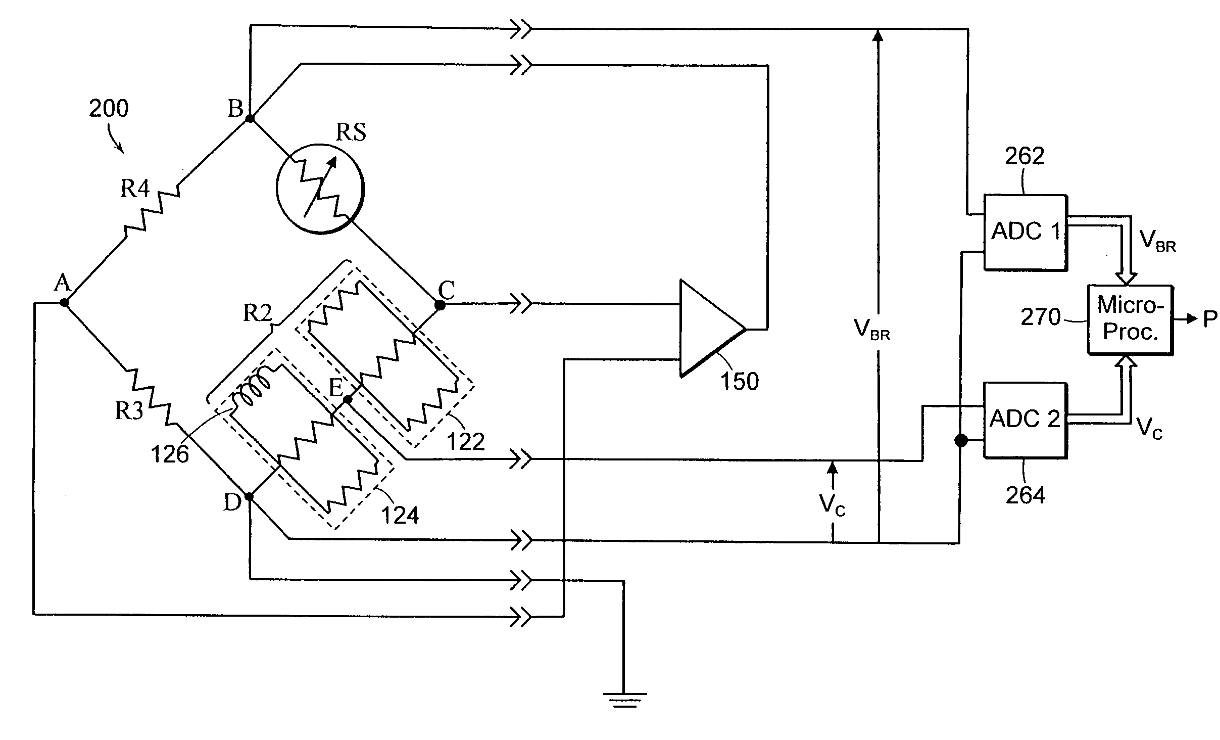
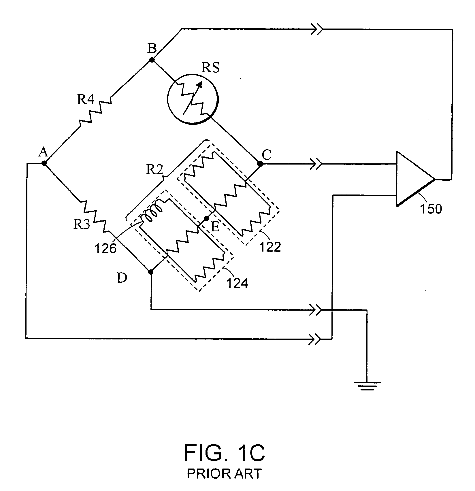
[0041]FIG. 2 illustrates a heat-loss gauge 200 according to one embodiment of the present invention. The heat-loss gauge may be implemented using a Wheatstone bridge configuration depicted in FIG. 1C. A first analog-to-digital-converter (ADC) 262 connects to nodes B and D to obtain the value of the overall bridge voltage (VBR). The first ADC 262 provides a digital value representing the overall bridge voltage to a microprocessor 270. A second ADC 264 connects to nodes D and E to obtain the value of the voltage across the temperature sensitive section 124 and to provide a digital value representing a compensator junction voltage (VC) to the microprocessor 270.

[0042]As the temperature changes at any given pressure, the compensator junction voltage (VC) at the junction of the temperature sensitive and the temperature stable sections 122, 124 will change as a percentage of the total bridge voltage (VBR). Thus, the pre...


PUM

PropertyMeasurementUnit
voltageaaaaaaaaaa
pressureaaaaaaaaaa
pressureaaaaaaaaaa

Abstract

A method and apparatus are provided for achieving nearly perfect temperature compensation of a heat-loss vacuum gauge over its full pressure range. A voltage is measured across a sensor leg, a sensor leg and a temperature compensating leg connected together in series, or a sensor leg and a fixed resistive leg coupled together in series. A voltage is also measured across a subleg of the temperature compensating leg. The temperature compensating leg may include a temperature sensitive subleg and a temperature stable subleg connected together in series. The sublegs may include one or more temperature sensitive and / or temperature stable elements. The measured voltages are combined to produce temperature independent pressure indications over a pressure range. Three-dimensional curve-fitting or similar techniques may be used to combine the measured voltages.

Description

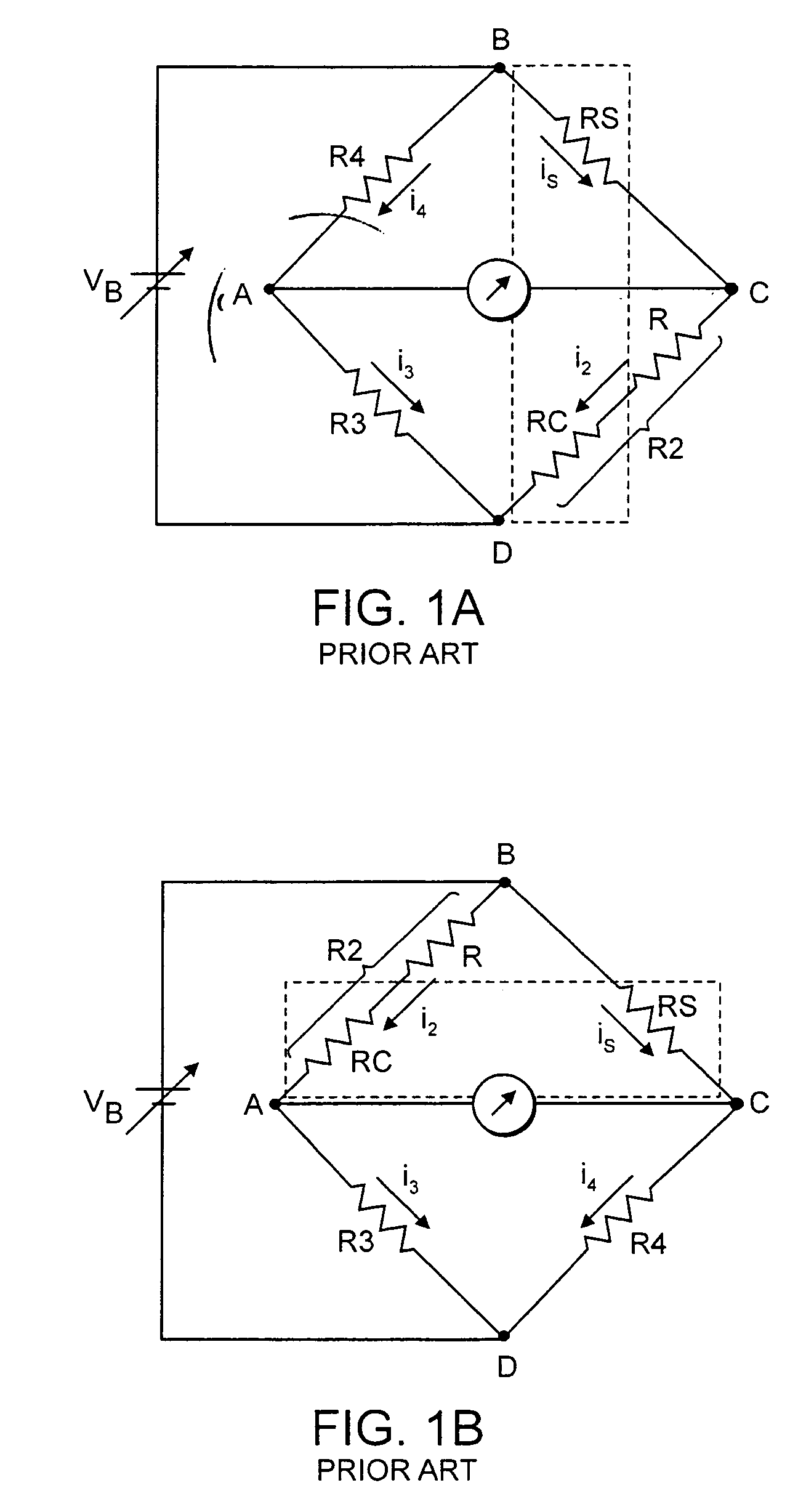
BACKGROUND OF THE INVENTION[0001]A heat-loss vacuum gauge may be used to determine gas pressure in an environment by measuring heat transfer rates from a heated sensing element to the gas under certain conditions. In a Pirani-type heat-loss vacuum gauge (“Pirani gauge”), heat transfer rates are measured using a Wheatstone bridge network, which serves both to heat the sensing element and to measure its resistance to obtain a pressure indication.[0002]FIG. 1A shows a simplified schematic diagram of a Wheatstone bridge network of a Pirani gauge. The Pirani gauge includes a temperature sensitive element RS connected between nodes B and C forming a temperature sensitive leg of the Wheatstone bridge. R2 is typically a temperature sensitive resistance designed to have a negligible temperature rise due to a current i2. R2 may include resistances R and RC connected in series between nodes C and D forming a temperature compensating leg of the Wheatstone bridge. R3 and R4 are typically fixed r...

Claims


Application Information

Patent Timeline
Patent Type & Authority Patents(United States)
IPC IPC(8): G01L19/04
CPCG01L21/12
Inventor BORENSTEIN, MICHAEL D.
Owner MKS INSTR INC
Learn More