
Low noise light receiver

a low-noise light and receiver technology, applied in the direction of instruments, counting objects on conveyors, satellite communication transmission, etc., can solve the problems of poor signal to noise ratio, large bandwidth and intensity of received light, etc., and achieve the effect of improving the signal to noise ratio

Inactive Publication Date: 2008-02-12
OPTOSYS SA
View PDF15 Cites 15 Cited by
  • Summary
  • Abstract
  • Description
  • Claims
  • Application Information

AI Technical Summary

Benefits of technology

[0010]Based on this prior art, it is an object of the present invention to provide a light receiver that remains operational even in conditions of intense ambient light but offers an improved signal to noise ratio.
[0012]The light receiver of the invention has the advantage that it is applicable also in conditions of intense ambient light and provides an improved signal to noise ratio.

Problems solved by technology

However, in almost every case, the conversion at a given signal bandwidth and intensity of the received light should be as noiseless as possible.
All the electrical circuits described in the US-patents mentioned above have the disadvantage that intense ambient light may cause a large shot noise resulting in a relatively poor signal to noise ratio.

Method used


Image

  • Low noise light receiver
  • Low noise light receiver
  • Low noise light receiver

Examples


Embodiment Construction

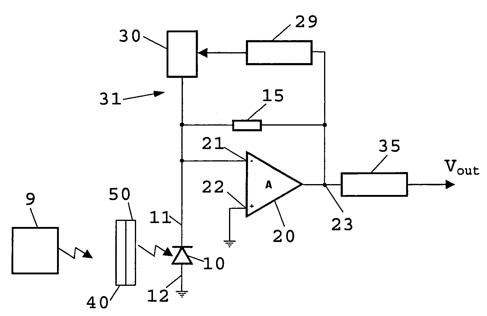
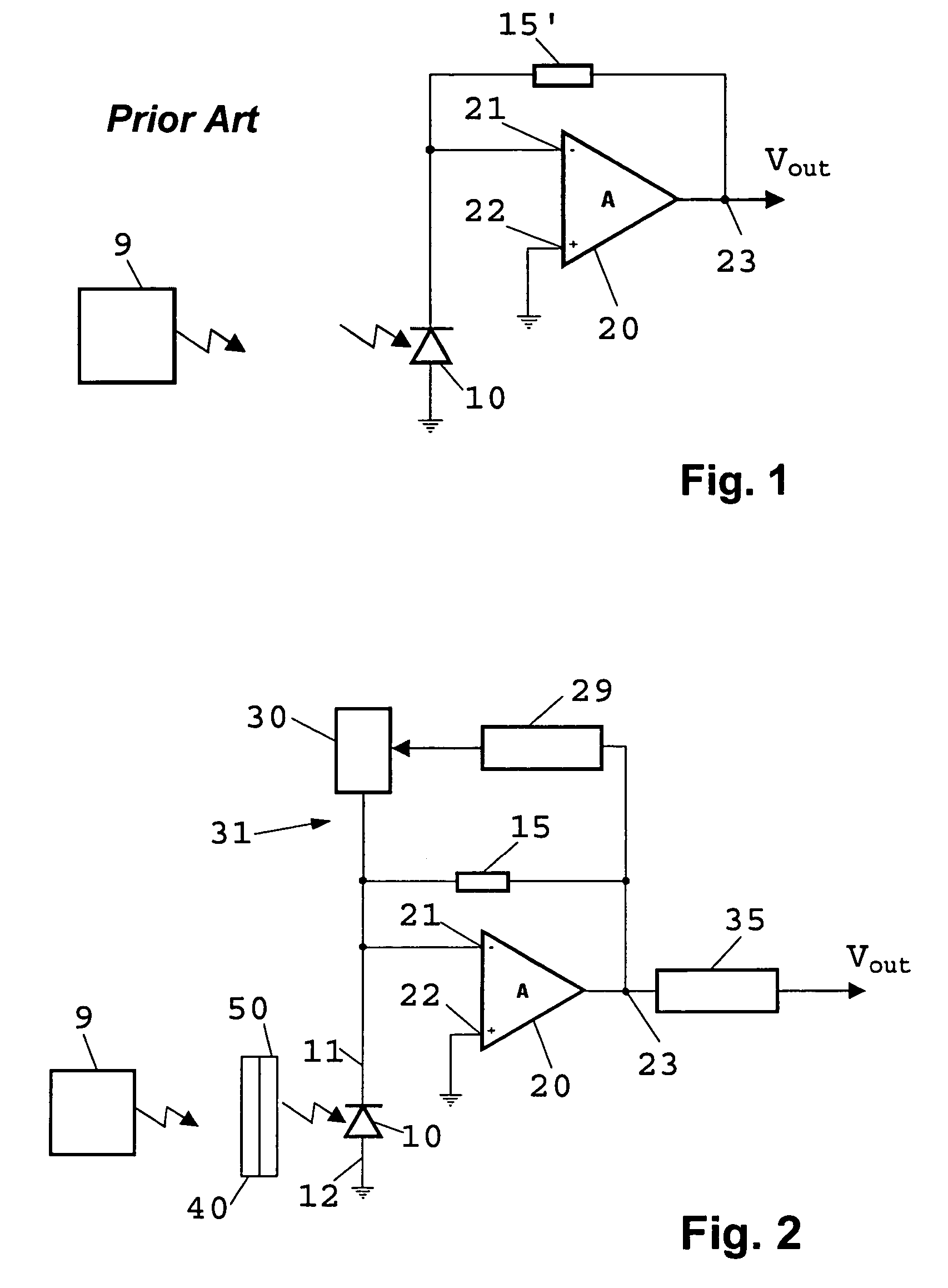
[0021]FIG. 1 shows a commonly used arrangement of photodiode 10 and amplifier 20. Photodiode 10 is connected to the inverting input 21 of amplifier 20 and via load resistor 15′ to output 23 of amplifier 20. The voltage Vout measured at output 23 is essentially proportional to the current generated by photodiode 10 when it receives the light signals emitted by a light source 9. Thus, the assembly of FIG. 1 acts as a current-voltage converter.

[0022]The principal noise sources of the assembly according to FIG. 1 are photodiode 10 and load resistor 15′. On the other hand, the noise produced by amplifier 20 is negligible in the intense ambient light that may be present in sensory applications. Due to thermal noise, load resistor 15′ produces a noise current that represents the major part of the overall noise. Now, a fundamental disadvantage of the assembly according to FIG. 1 is that load resistor 15′ must be dimensioned such that a saturation of amplifier 20 is excluded even if intense ...


PUM


Abstract

The low noise light receiver comprises a light sensor for generating a sensor signal, the sensor signal comprising a wanted signal resulting from a light source and an interfering signal resulting from interfering light; an optical filter apparatus for reducing the interfering light; an electric filter apparatus connected to the light sensor for filtering out the interfering signal and for generating a correction signal that substantially compensates for the interfering signal; and a processing apparatus connected to the light sensor and the electric filter apparatus for processing the wanted signal in order to generate an output signal (Vout).

Description

FIELD OF THE INVENTION[0001]The invention refers to a low noise light receiver comprising a light sensor and processing means for generating an output signal.BACKGROUND OF THE INVENTION[0002]In the conversion of light into electric current for the purpose of signal transmission, the requirements may vary and numerous realizations are possible. However, in almost every case, the conversion at a given signal bandwidth and intensity of the received light should be as noiseless as possible.[0003]A component that is very frequently used for the conversion of light signals into electric signals is the photodiode. In many cases, it is superior to other converters. Since the electric signal delivered by a photodiode is normally very weak, it must be amplified by means of an amplifier in order to be utilized. At a given bandwidth and intensity of the received light, the photodiode and the amplifier largely determine the signal to noise ratio of the signal available at the output of the ampli...

Claims


Application Information

Patent Timeline
Patent Type & Authority Patents(United States)
IPC IPC(8): H04B10/06H04B10/2507H03F1/26H03F3/08H03F3/45H04B10/07H04B10/11H04B10/118H04B10/40H04B10/43H04B10/50H04B10/60H04B10/67H04B10/69
CPCH03F1/26H03F3/087H03F3/45475H03F2200/372
Inventor HEIMLICHER, PETER
Owner OPTOSYS SA
Learn More