Electro-optical apparatus, its production method, devices and electronic appliances

a technology of optical apparatus and production method, applied in the field of optical apparatus, can solve the problems of product defect, subject of related art technology described above, etc., and achieve the effect of reducing the occurrence of disconnection

Inactive Publication Date: 2008-02-12
KATEEVA
View PDF11 Cites 4 Cited by
  • Summary
  • Abstract
  • Description
  • Claims
  • Application Information

AI Technical Summary

Benefits of technology

[0012]Therefore, even when wettability to the protective layer is different between the shading layer and the partition layer, the shading layer does not come into contact with the protective layer, and instead the partition layer comes into contact with the protective layer. In consequence, a sharp change of the protective layer resulting from the difference of wettability can be reduced or suppressed. Since deformation of the electrode on the protective layer can be eventually mitigated, the occurrence of disconnection can be reduced.
[0014]Consequently, the sharp change resulting from the difference of wettability can be reduced or suppressed in the invention, even when the thickness of the protective layer changes at the boundary between the portion at which the shading layer, the partition layer and the color filter are arranged and the portion at which they are not.
[0016]According to the invention, therefore, the sharp change of the protective layer resulting from the difference of wettability can be reduced or suppressed, even when the shading layer is formed of a metal material, such as Cr, the partition layer is formed of a polymer, resin and the protective layer is formed of a synthetic resin material, such as an acrylic resin, for example.
[0018]Consequently, the invention can reduce the occurrence of disconnection in the device and can enhance its quality. An organic EL light emitting layer and a micro-lens array can be applied to the functional layer.
[0020]Therefore, the invention can reduce the occurrence of disconnection and can enhance quality of the electronic appliance.
[0022]Therefore, even when wettability to the protective layer is different between the shading layer and the partition layer in the invention, the shading layer does not come into contact with the protective layer, and instead the partition layer comes into contact with the protective layer. For this reason, the sharp change of the protective layer resulting from the difference of wettability can be suppressed with the result that deformation of the electrode on the protective layer can be mitigated and the occurrence of disconnection can be reduced.

Problems solved by technology

However, the related art technology described above is subject to the following problem.
As a result, an electrode 7 extending on the surface of the protective layer is likely to undergo disconnection in the proximity of the portion B and the resulting product becomes defective.

Method used


Image

  • Electro-optical apparatus, its production method, devices and electronic appliances
  • Electro-optical apparatus, its production method, devices and electronic appliances
  • Electro-optical apparatus, its production method, devices and electronic appliances

Examples


Embodiment Construction

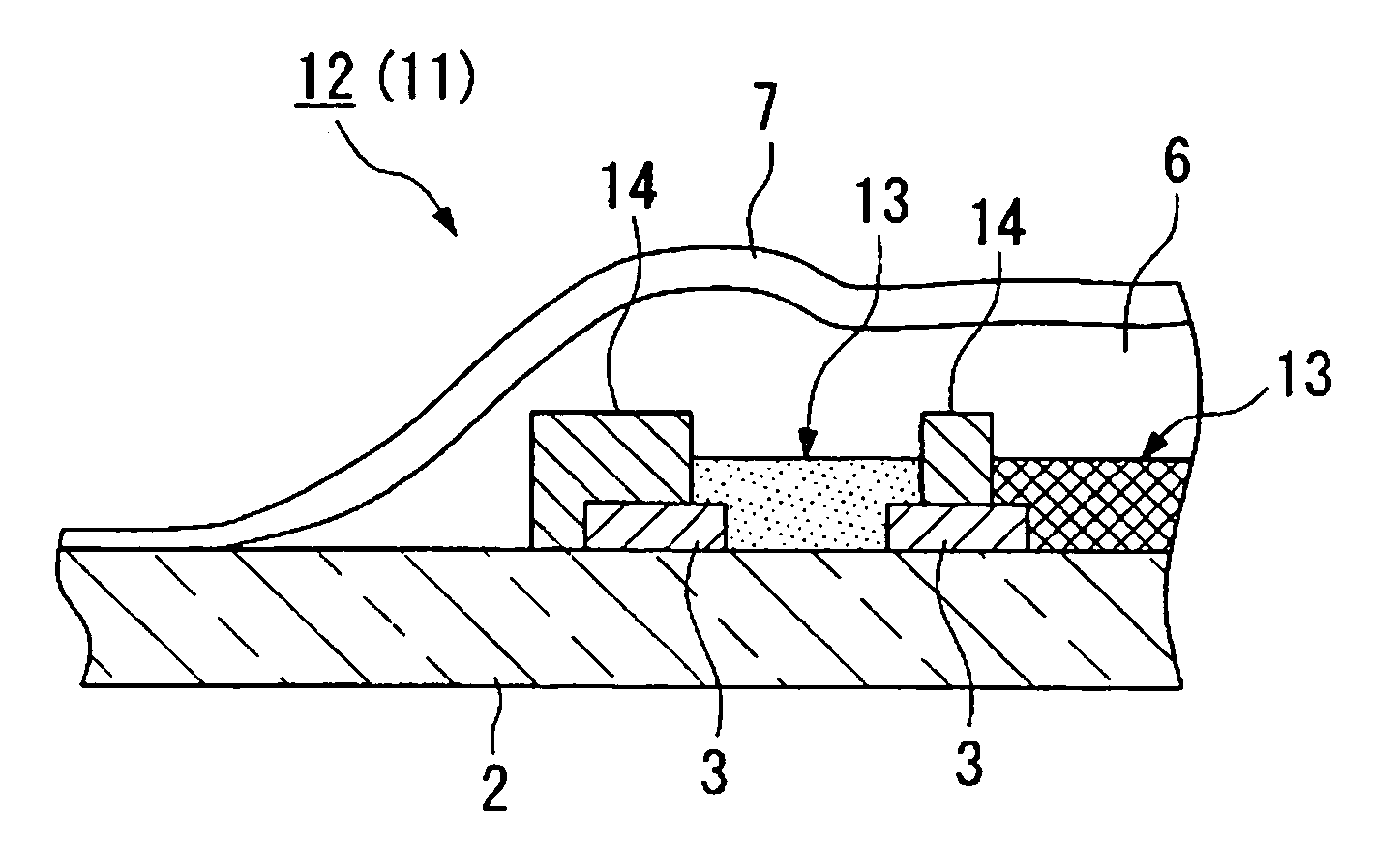
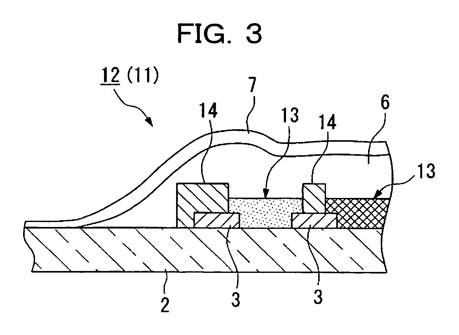
[0029]An electro-optical apparatus and its production method, devices and electronic appliances according to the invention are hereinafter explained with reference to FIGS. 1 to 5(c). Explanation is provided of production of a color filter as a component of an electro-optical apparatus by way of example. In these drawings, the same references are used to identify the same constituent elements shown in FIG. 6 as an example of the related art and explanation of such constituent elements is omitted.

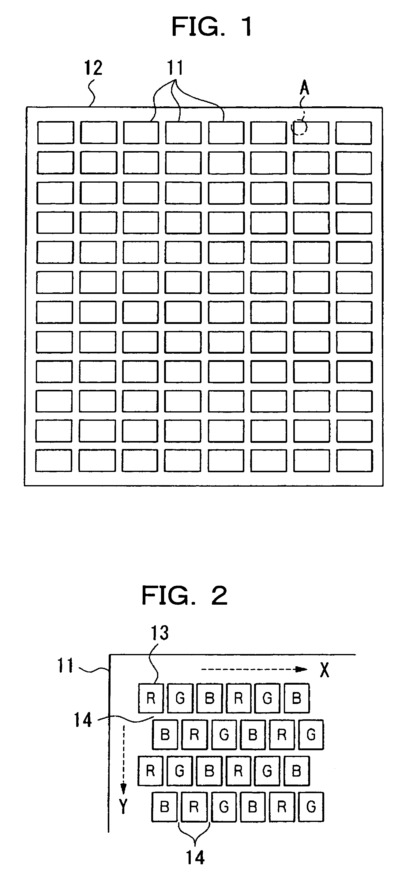
[0030]FIG. 1 is a plan view showing a planar shape of a color filter substrate used to produce the color filter in this exemplary embodiment. FIG. 2 is an enlarged view of a portion sign A in FIG. 1.

[0031]In the color filter substrate 12 shown in FIG. 1, a plurality of panel chips 11 that constitute one color filter is aligned on a plane. In this exemplary embodiment, one color filter substrate 12 includes about 100 panel chips 11. During the production of the color filter, ink jet and dryin...


PUM

PropertyMeasurementUnit
wettabilityaaaaaaaaaa
alkalineaaaaaaaaaa
timeaaaaaaaaaa

Abstract

The invention mitigates a drop of a protective layer and reduces disconnection of an electrode. A shading layer, a partition layer to partition a color filter layer, formed on the shading layer, and a protective layer to seal the shading layer, the partition layer and the color filter layer, are arranged on a substrate. At least a part of the partition layer covers the shading layer and separates the protective layer from the shading layer under a non-contact state.

Description

[0001]This is a Divisional of U.S. patent application Ser. No. 10 / 396,335 filed Mar. 26, 2003 now U.S. Pat. No. 7,106,399, which is hereby incorporated by reference in its entirety. This application claims priority to Japanese Patent Application No. 2002-89811 filed Mar. 27, 2002, which is hereby incorporated by reference in its entirety.BACKGROUND OF THE INVENTION[0002]1. Field of Invention[0003]This invention relates to an electro-optical apparatus, such as a color filter, an electroluminescence device matrix, its production method, devices and electronic appliances.[0004]2. Description of Related Art[0005]The related art includes an electro-optical apparatus equipped with a color filter, etc., that uses the application of an ink jet method. FIG. 6 shows an example of a color filter substrate. In the color filter substrate 1 shown in FIG. 6, a shading layer 3 formed of Cr, or the like, and referred to as “black matrix”, and a bank 4 operating as a partition of ink, are implanted o...

Claims


Application Information

Patent Timeline
Patent Type & Authority Patents(United States)
IPC IPC(8): G02F1/1333B41J2/01G02B5/20G02F1/1335G09F9/00G09F9/30H01L27/32
CPCG02F1/1333G02F1/1335
Inventor KIGUCHI, HIROSHIKATAGAMI, SATORU
Owner KATEEVA
Why Eureka
Try Eureka