
Differential amplifier with cascade control

a technology of cascade control and amplifier, which is applied in the direction of differential amplifiers, amplifiers with semiconductor devices/discharge tubes, dc-amplifiers with dc-coupled stages, etc. it can solve the problems of low efficiency, analog amplifiers, and relatively high power consumption of amplifiers for generating high output, so as to increase the gain of differential amplifiers

Active Publication Date: 2008-02-12
SAMSUNG ELECTRONICS CO LTD
View PDF7 Cites 38 Cited by
  • Summary
  • Abstract
  • Description
  • Claims
  • Application Information

AI Technical Summary

Benefits of technology

[0013]A differential amplifier according to the present invention has class AB control with cascode load for increased gain and reduced offset.
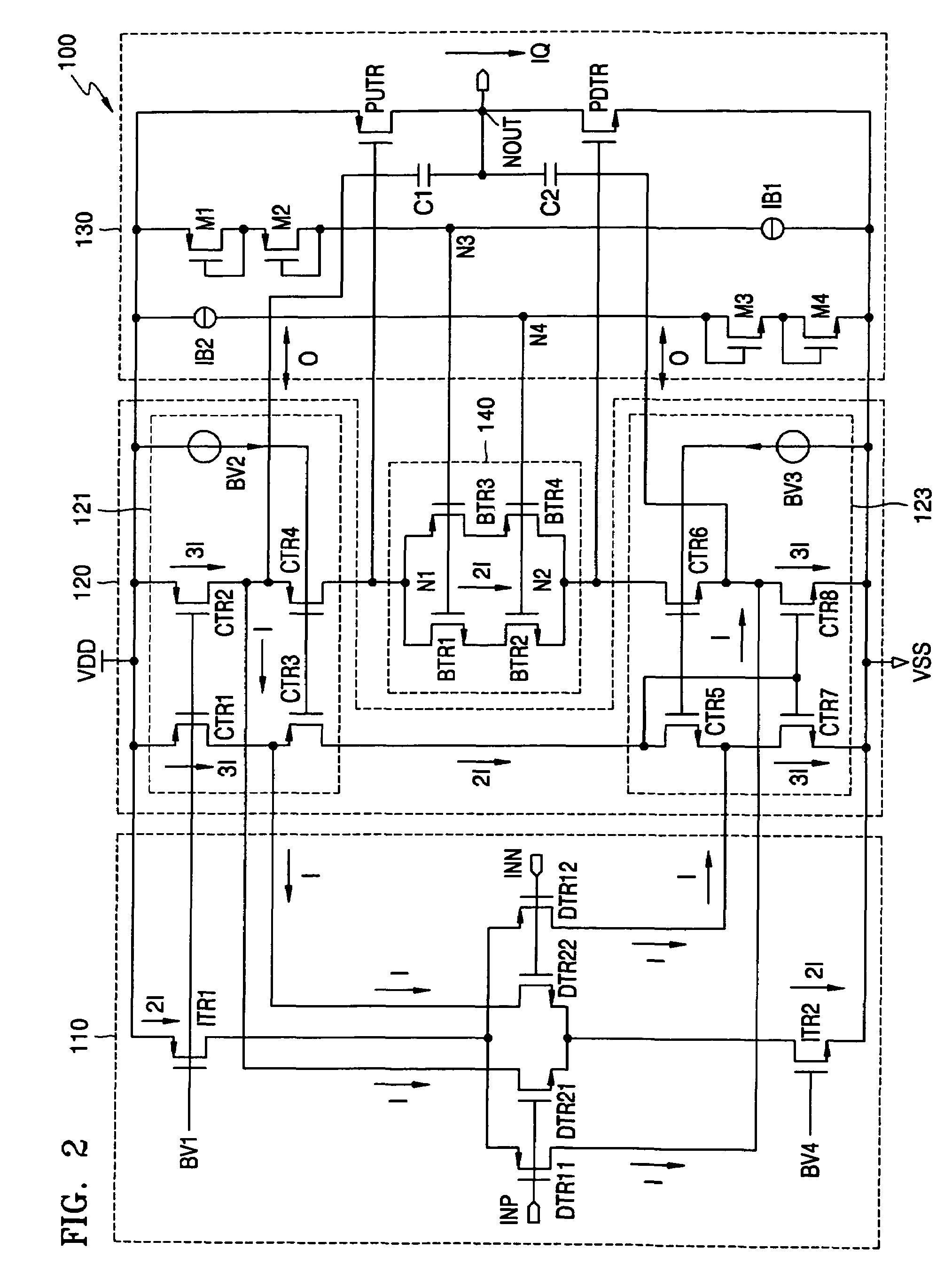
[0022]In this manner, with cascode loading from the cascode current mirrors and the floating current source, the gain of the differential amplifier is increased.

Problems solved by technology

However, such amplifiers consume relatively high power for generating high output.
That is, analog amplifiers have the advantage of high linearity, but the disadvantage of low efficiency.
However, the class B push-pull amplifier has crossover distortion for low signal levels.
Further, although the transistors of the class B push-pull amplifier are easily turned on and off for small currents, such transistors cannot be rapidly turned on and off for large currents.
More specifically, since no bias current flows in the class B amplifier when in an idle (i.e., static) state, it is difficult to rapidly turn the transistors on / off for large currents resulting in increased total harmonic distortion (THD).

Method used


Image

  • Differential amplifier with cascade control
  • Differential amplifier with cascade control
  • Differential amplifier with cascade control

Examples


Embodiment Construction

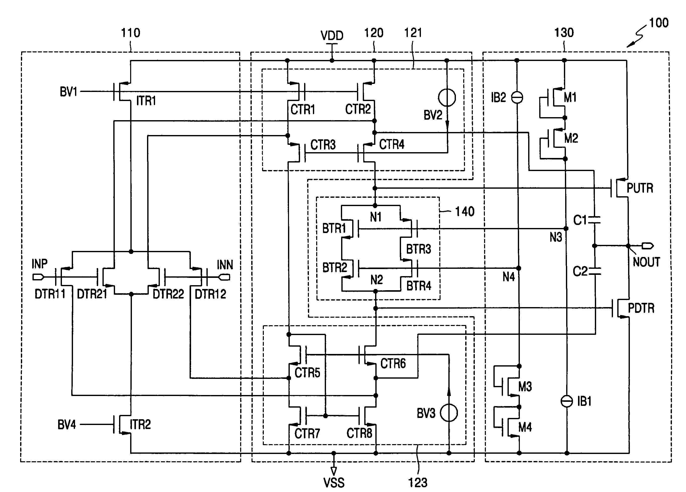
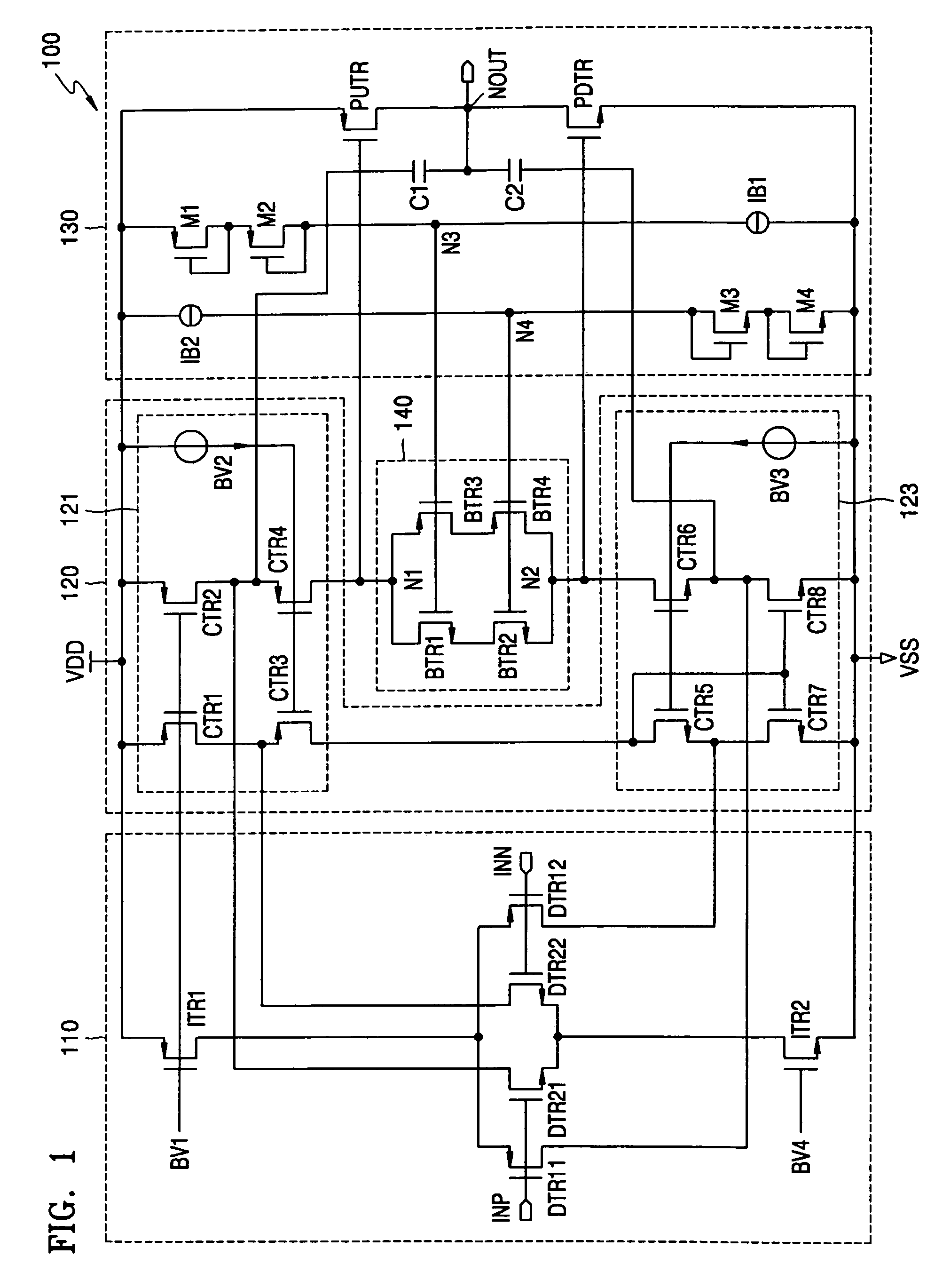
[0029]FIG. 1 shows a circuit diagram of a differential amplifier 100 according to an embodiment of the present invention. Referring to FIG. 1, the differential amplifier 100 includes an input stage 110, a current summing circuit 120, an output stage 130, and a floating current source 140.

[0030]The input stage 110 includes a pair of differentially coupled PMOSFETs (P-channel metal oxide semiconductor field effect transistors) DTR11 and DTR12 coupled to a high power supply VDD through another PMOSFET ITR1. Further, the input stage 110 includes a pair of differentially coupled NMOSFETs (N-channel metal oxide semiconductor field effect transistors) DTR21 and DTR22 coupled to a low power supply VSS through another NMOSFET ITR2. The low power supply VSS may be the ground node for example.

[0031]The input stage 110 is a folded cascode operational transconductance amplifier (OTA). The folded cascode OTA converts a voltage difference between differential input signals INP and INN into differe...


PUM


Abstract

A differential amplifier includes an input stage, an output stage, and a control unit. The input stage generates differential currents in response to a voltage difference between differential input signals. The output stage generates an output signal at an output node. The control unit is coupled between the input stage and the output stage and includes a floating current source comprised of a cascode load for biasing the output stage with a quiescent current. Such a cascode load increases DC gain of the differential amplifier.

Description

BACKGROUND OF THE INVENTION[0001]This application claims priority to Korean Patent Application No. 2004-77157, filed Sep. 24, 2004 in the Korean Intellectual Property Office, the disclosure of which is incorporated herein in its entirety by reference.[0002]1. Field of the Invention[0003]The present invention relates to differential amplifiers, and more particularly, to a differential amplifier having class AB control with cascode loading for increased gain and reduced offset.[0004]2. Description of the Related Art[0005]A push-pull amplifier circuit including CMOS (complementary metal oxide semiconductor) transistors is an often used circuit. An audio amplifier circuit is typically an analog amplifier circuit or a digital amplifier circuit.[0006]An analog amplifier circuit is classified into one of a class A amplifier circuit, a class B amplifier circuit, or a class AB amplifier circuit, and a digital amplifier circuit is classified as a class D amplifier circuit. Since linearity is ...

Claims


Application Information

Patent Timeline
Patent Type & Authority Patents(United States)
IPC IPC(8): H03F3/45
CPCH03F3/3022H03F3/45192H03F2203/45288H03F2203/45366H03F3/45
Inventor KANG, JAE-SUNGPARK, CHANG-MI
Owner SAMSUNG ELECTRONICS CO LTD
Learn More