
Single point sensing for end of lamp life, anti-arcing, and no-load protection for electronic ballast

a technology of electronic ballast and end of lamp life, which is applied in the direction of instruments, process and machine control, and can solve the problems of lamp end caps and holders exceeding the design temperature limit, and affecting the safety and reliability of lighting systems. , to achieve the effect of convenient single-point sensing

Inactive Publication Date: 2008-02-05
GENERAL ELECTRIC CO
View PDF9 Cites 28 Cited by
  • Summary
  • Abstract
  • Description
  • Claims
  • Application Information

AI Technical Summary

Benefits of technology

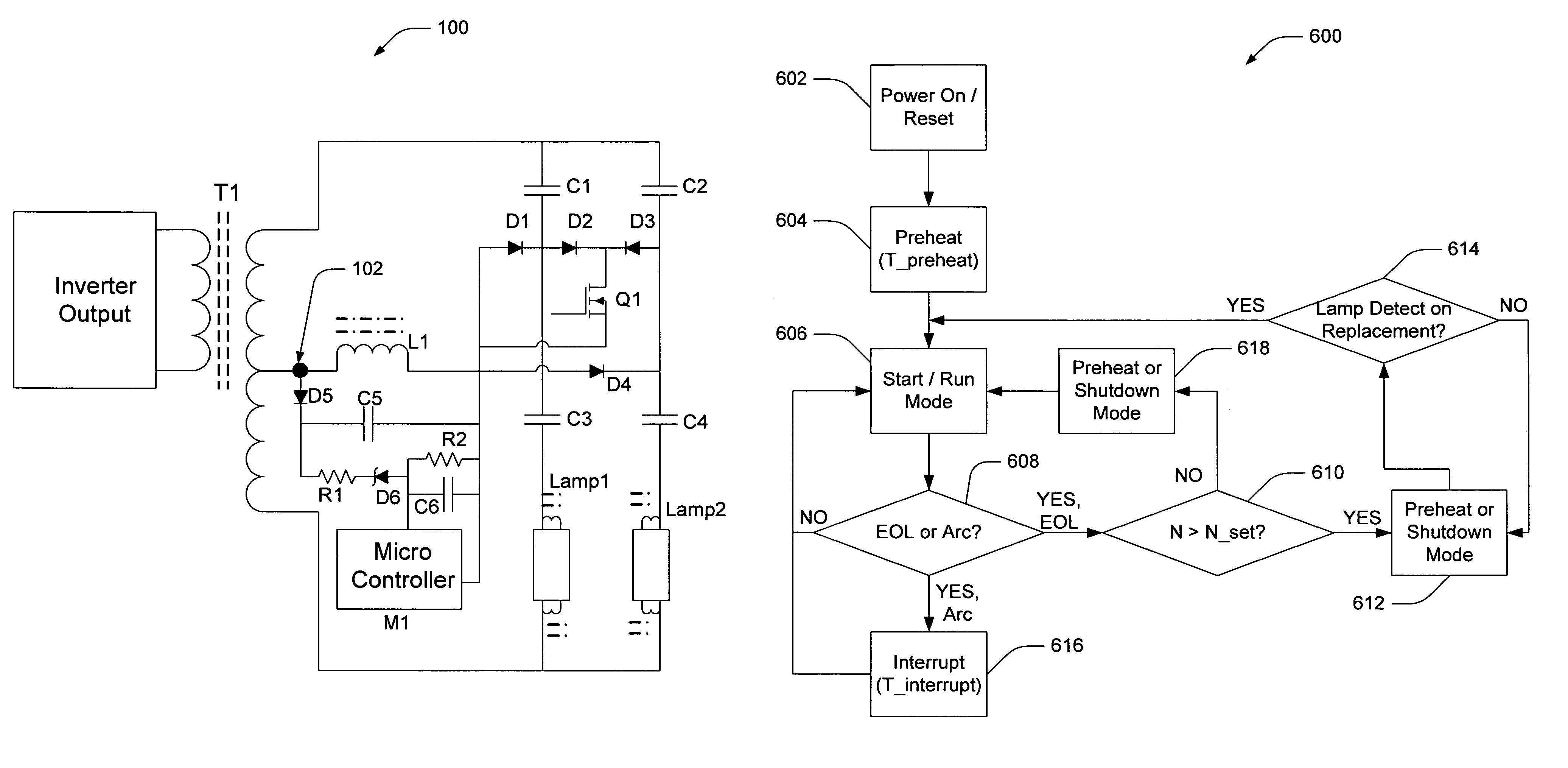
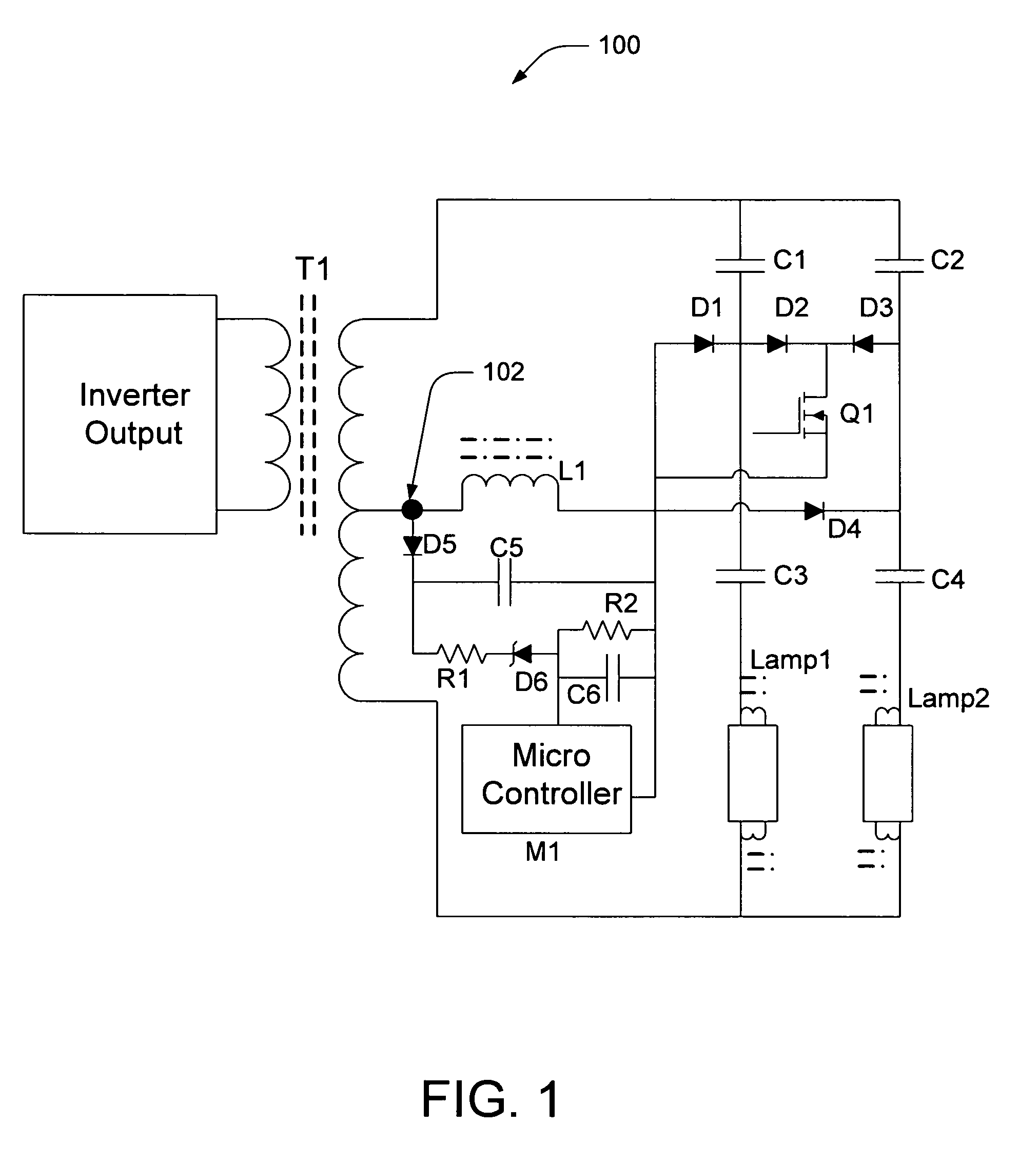
[0003]According to one or more aspects, a system that facilitates single-point sensing of end-of-life, anti-arcing, and no-load protection for an electronic ballast may comprise a first capacitor, a second capacitor, and a diode that experience a step change in one or more of current and voltage upon the occurrence of a pulsing event in a first lamp connected in series with the first and second capacitors; and a controller that detects the step change in the one or more of current and voltage and initiates a responsive action to the pulsing event as a function of information associated with at least one pulse.

Problems solved by technology

However, a small diameter lamp may raise certain concerns, especially when a lamp approaches the end of its life (EOL).
For instance, some lamps' end caps can overheat due to a depletion of an emission mix in the filament as they approach the EOL stage, and due to a small spacing between the cathode and lamp wall.
When this occurs, the lamp's end cap and holder may exceed a design temperature limit and detrimentally affect the safety and reliability of the lighting system.

Method used


Image

  • Single point sensing for end of lamp life, anti-arcing, and no-load protection for electronic ballast
  • Single point sensing for end of lamp life, anti-arcing, and no-load protection for electronic ballast
  • Single point sensing for end of lamp life, anti-arcing, and no-load protection for electronic ballast

Examples


Embodiment Construction

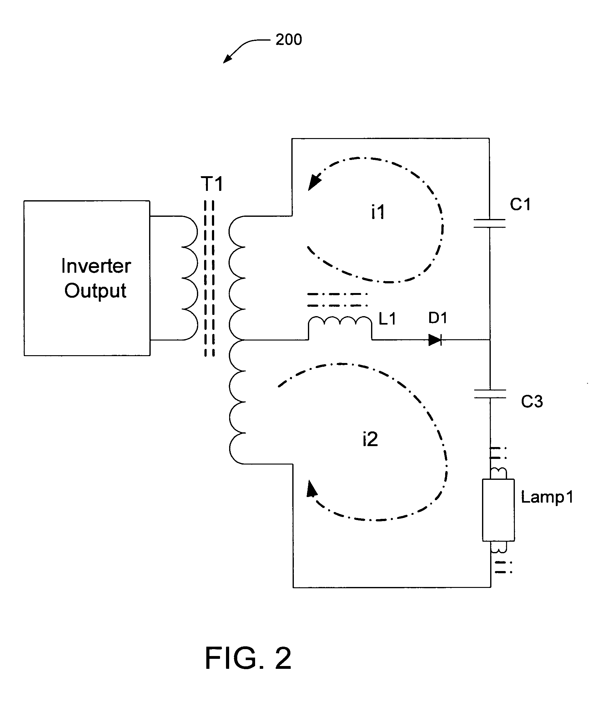
[0012]Conventional ballasts implement lamps in series and senses lamp rectification by using either over-voltage (e.g., wherein the lamp increases voltage as the e-mix in the cathode depletes) or by sensing voltage developed on a DC blocking capacitor when the rectified current goes through it. If the measured voltage is outside of a window of predetermined minima and maxima, a protection circuit typically responds by shutting down the ballast.

[0013]However, there are many deficiencies associated with the over-voltage sensing approach. First, the ballast needs to be able to support multiple wattages and lamp lengths that operate at different voltages. Second, the problem becomes even more pronounced when two or more lamps operate in a series configuration. Ballasts designed with such a detecting method often do not work reliably and may cause malfunction, even when the lamp is in good condition. In some cases, a protection circuit may react by initiating a ballast starting sequence,...


PUM


Abstract

Systems and methods are disclosed that facilitate sensing a pulse in a ballast circuit for a lamp when the lamp is in an end-of-life (EOL) stage or when the lamp is experiencing an arcing conduction condition, such as may occur when a contact between the lamp and its holder is compromised. Upon sensing the pulse, a microcontroller may distinguish between EOL and arcing conditions based on detected pulse width(s), and may initiate an appropriate response. For instance, if the pulse is due to an arcing event, the microcontroller may interrupt lamp operation for a brief period before restarting the lamp to mitigate the arcing condition. If the pulse is caused by an EOL condition, the microcontroller may place the lamp in a preheat or restarting mode to hasten lamp failure. In either case, responses to the sensed pulse mitigate the occurrence of dangerously high lamp temperatures that may damage lamp sockets.

Description

BACKGROUND OF THE INVENTION[0001]When designing lamps and associated circuitry, economic considerations are of paramount importance and often are the difference between an acceptable design and an optimal design. Modern lamps come in a variety of sizes to accommodate multiple design variations. For instance, a T8 lamp size is approximately one inch in diameter, while a T12 lamp is approximately one and a half inches in diameter. Other sizes are also available to meet designer and consumer needs.[0002]The T5 lamp and ballast have gained increasing popularity due in part to its compact size and high lumen efficacy relative to other ballast-and-lamp systems. However, a small diameter lamp may raise certain concerns, especially when a lamp approaches the end of its life (EOL). For instance, some lamps' end caps can overheat due to a depletion of an emission mix in the filament as they approach the EOL stage, and due to a small spacing between the cathode and lamp wall. When this occurs,...

Claims


Application Information

Patent Timeline
IPC IPC(8): G05F1/00
CPCH05B41/2985H05B41/2988Y10S315/05
Inventor CHEN, TIMOTHYHARI, AJAY KARTHIKHARPER, GREGORY ALAN
Owner GENERAL ELECTRIC CO
Learn More