
Multi-reflecting time-of-flight mass spectrometer with isochronous curved ion interface

a time-of-flight, multi-reflecting technology, applied in the field of mass spectroscopic analysis, can solve the problems of limiting the maximum mass range, limiting the acceptable mass range, and most of the multi-reflecting and multi-turn instruments of the prior art not providing the full mass rang

Active Publication Date: 2008-02-05
LECO CORPORATION
View PDF10 Cites 91 Cited by
  • Summary
  • Abstract
  • Description
  • Claims
  • Application Information

AI Technical Summary

Benefits of technology

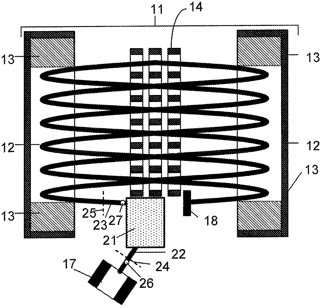
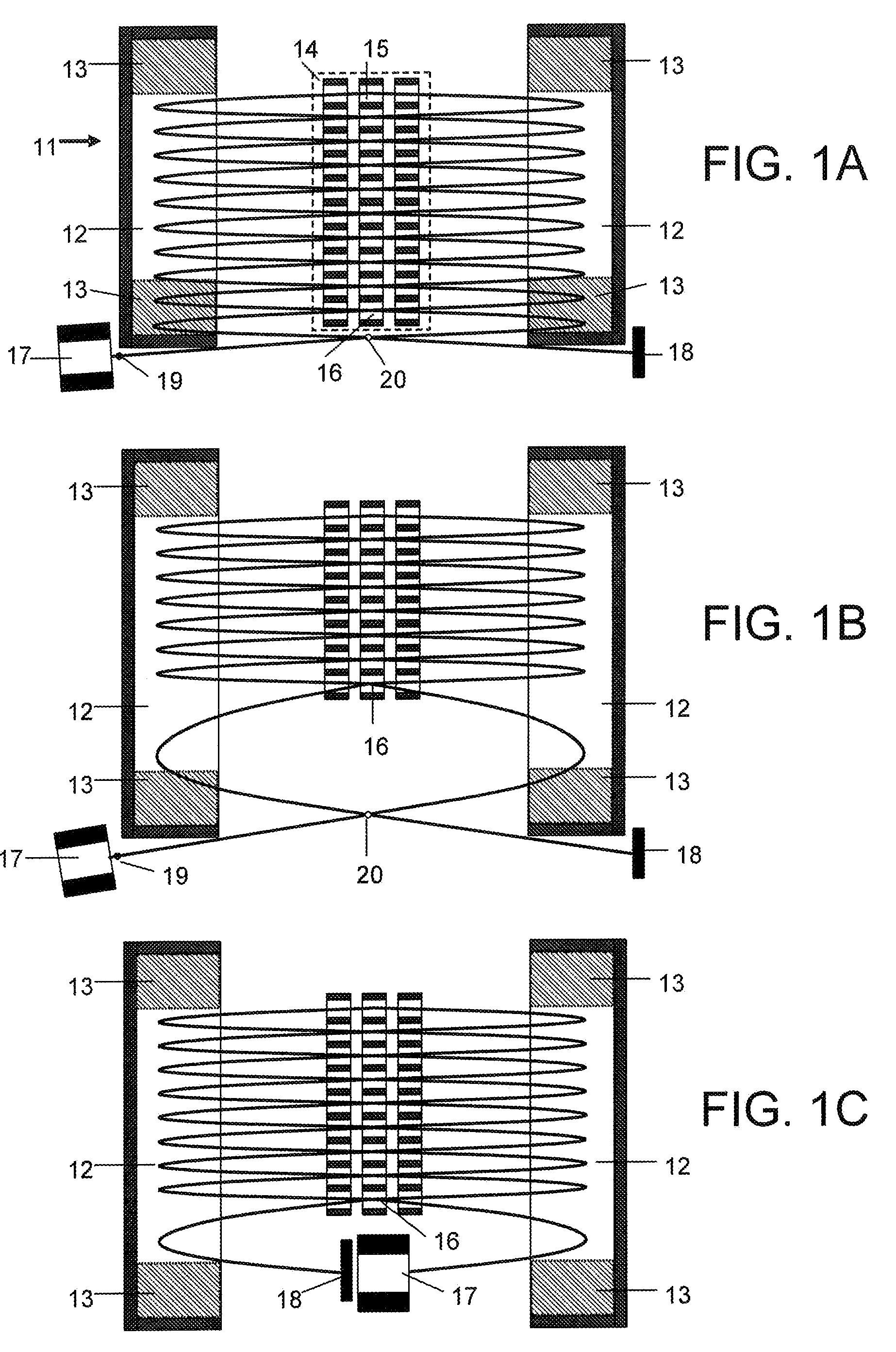
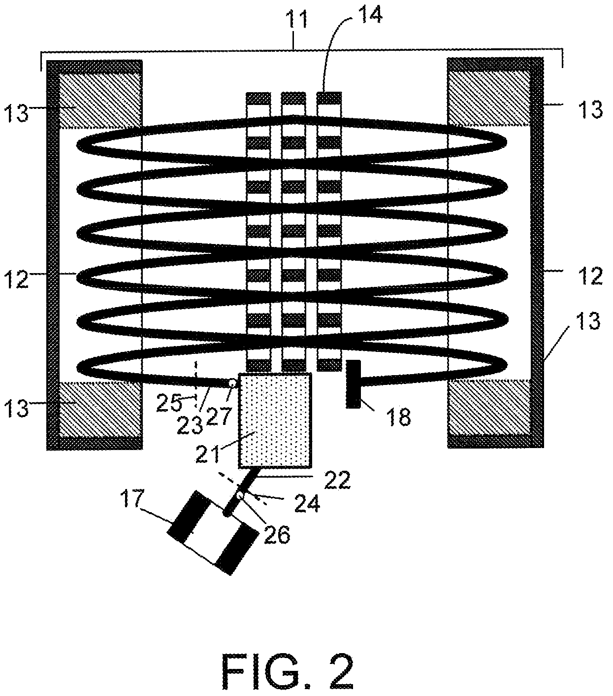
The present invention provides a multi-reflecting time-of-flight mass spectrometer apparatus that includes an ion source, a planar multi-reflecting time-of-flight analyzer, an ion receiver, and a spatially isochronous ion transfer interface. The spatially isochronous ion transfer interface includes at least one electrostatic sector with a curved axis. The invention also provides a hybrid time-of-flight mass analyzer apparatus that includes at least one spatially isochronous set of electrostatic sectors, an ion mirror, and an ion receiver. The invention also includes an apparatus with a pulsed ion source, a multi-reflecting time-of-flight analyzer, an ion receiver, and at least one spatially isochronous ion transfer interface. The technical effects of the invention include improved accuracy and resolution in mass spectrometry analysis and reduced aberration.

Problems solved by technology

However, ultimate parameters of the scheme are limited by a pulsed ion injection.
As in the previous case, multiple reflections automatically limit an acceptable mass range.
Most of the multi-reflecting and multi-turn instruments of the prior art do not provide for the full mass range, since ion trajectories are closed into loops.
However, gradual expansion of ion packets causes spatial overlapping of ion trajectories at the adjacent reflections.
The steering causes tilting of time fronts.Second, the injected ion packets appear close to the mirror edges where the electrostatic field is distorted which may thus cause time aberrations.
However, as described below with respect to FIGS. 1A-1C, this is not practical with existing sources and detectors.Third, the remote location of the ion source shifts the intermediate time focal planes from their optimal positions at the MR TOF axis and thus compromises the initial parameters of the ion packets and degrades the overall resolving power of the MR TOF MS.
Still, the initial parameters of the ion packets in the source define time and energy spread of the ion packets, which is the second major limiting factor on MR TOF resolution.
This inevitably raises the energy spread of ion packets.
The resolution is primarily limited by ion injection around the edges of the ion mirrors.
The second limiting factor is the phase space of the ion packets in the ion source, particularly when using ion trap converters.

Method used


Image

  • Multi-reflecting time-of-flight mass spectrometer with isochronous curved ion interface
  • Multi-reflecting time-of-flight mass spectrometer with isochronous curved ion interface
  • Multi-reflecting time-of-flight mass spectrometer with isochronous curved ion interface

Examples


embodiment 111

[0162]Referring to FIG. 11, a preferred embodiment 111 of the third aspect of the invention comprises a rectilinear ion trap 112 with delayed extraction, a C-shaped cylindrical interface 113 and a planar MR TOF analyzer 116. It also may comprise an optional second isochronous interface 114 and an external ion detector (receiver) 115. The long side of linear trap 112 is oriented across the plane of jig-saw ion trajectory in the MR TOF MS (here perpendicular to the drawing plane). An extracting pulse is applied after some predetermined delay (in microsecond time scale) after switching off the RF signal on the trap. Non-correlated velocity spread is reduced. An excessive energy is filtered out in the energy analyzer. Ion packets are ejected along a slightly tilted trajectory 117 to be aligned with the drift angle of the planar MR TOF analyzer with periodic lenses. In the particular embodiment, the ions are reflected in the last lens. This reverses the drift motion and doubles the fligh...

embodiment 121

[0165]Referring to FIG. 12A, in one particular embodiment 121, an isochronous cylindrical interface 122 with 180 degree deflection is suggested to transfer ions between two parallel ion mirrors—one mirror 123 sitting on the top of another 124. The arrangement opens ion access in and out of the planar ion mirror far from fringing fields in the mirror. An exemplar ion source 126 is shown opposite of the lower mirror 124.

[0166]FIG. 12B shows a three-dimensional view of the same embodiment 121, also showing an ion detector 127 at the back side of the MR TOF analyzer.

embodiment 131

[0167]Referring to FIG. 13, in another particular embodiment 131, a curved and spatially isochronous interface 132 is employed to transfer ions between at least two parallel MR TOF analyzers 133 and 134, aligned into a multi-level assembly. Isochronous curved interfaces are used to pass ions between the floors.

[0168]Both above embodiments maximize the ion path per vacuum chamber size. Multiple parallel mirrors could be conveniently and inexpensively made by machining multiple windows within the same electrodes.

[0169]An isochronous interface can be also employed to reverse the direction of ion drift motion (not shown). It could be used to transfer ions between different analyzers while being pulsed and static operated (not shown) or between multiple stages of tandem mass spectrometric analysis (described below). The curved sector is preferably made cylindrical for simpler manufacturing and alignment.

[0170]It is of significance that systems based on electrostatic sectors are usually e...


PUM


Abstract

The present invention relates generally to a multi-reflecting time-of-flight mass spectrometer (MR TOF MS). To improve mass resolving power of a planar MR TOF MS, a spatially isochronous and curved interface may be used for ion transfer in and out of the MR TOF analyzer. One embodiment comprises a planar grid-free MR TOF MS with periodic lenses in the field-free space, a linear ion trap for converting ion flow into pulses and a C-shaped isochronous interface made of electrostatic sectors. The interface allows transferring ions around the edges and fringing fields of the ion mirrors without introducing significant time spread. The interface may also provide energy filtering of ion packets. The non-correlated turn-around time of ion trap converter may be reduced by using a delayed ion extraction from the ion trap and excessive ion energy is filtered in the curved interface.

Description

CROSS-REFERENCE TO RELATED APPLICATION[0001]This application claims priority under 35 U.S.C. §119(e) on U.S. Provisional Patent Application No. 60 / 664,062 filed on Mar. 22, 2005, entitled “MULTI-REFLECTING TIME-OF-FLIGHT MASS SPECTROMETER WITH AN ENERGY FILTER,” and filed on behalf of Anatoli N. Verentchikov et. al., the entire disclosure of which is incorporated by reference herein.BACKGROUND OF THE INVENTION[0002]The present invention generally relates to the area of mass spectroscopic analysis, and more particularly relates to mass spectrometer apparatus, including a multi-reflecting time-of-flight mass spectrometer (MR TOF MS) and a method of use.[0003]Time-of-flight mass spectrometers (TOF MS) are increasingly popular—both as stand-alone instruments and as a part of mass spectrometry tandems with another TOF (TOF-TOF), with a quadrupole filter (Q-TOF), or with an ion trap (ITMS-TOF). They provide a unique combination of high speed, sensitivity, mass resolving power (hereinafter...

Claims


Application Information

Patent Timeline
Patent Type & Authority Patents(United States)
IPC IPC(8): H01J49/40
CPCH01J49/406H01J49/408H01J49/48H01J49/0004
Inventor VERENTCHIKOV, ANATOLI N.YAVOR, MIKHAIL
Owner LECO CORPORATION
Learn More