
Single sideband optical transmitter

a single-sideband, optical transmitter technology, applied in the field of optical communication, can solve the problems of difficult upgrade of a communications network, high data rate optical communication system subject to the effects of chromatic dispersion, and optical loss that may not be acceptable for high bit rate systems

Inactive Publication Date: 2008-01-29
MASSACHUSETTS INST OF TECH
View PDF13 Cites 3 Cited by
  • Summary
  • Abstract
  • Description
  • Claims
  • Application Information

AI Technical Summary

Benefits of technology

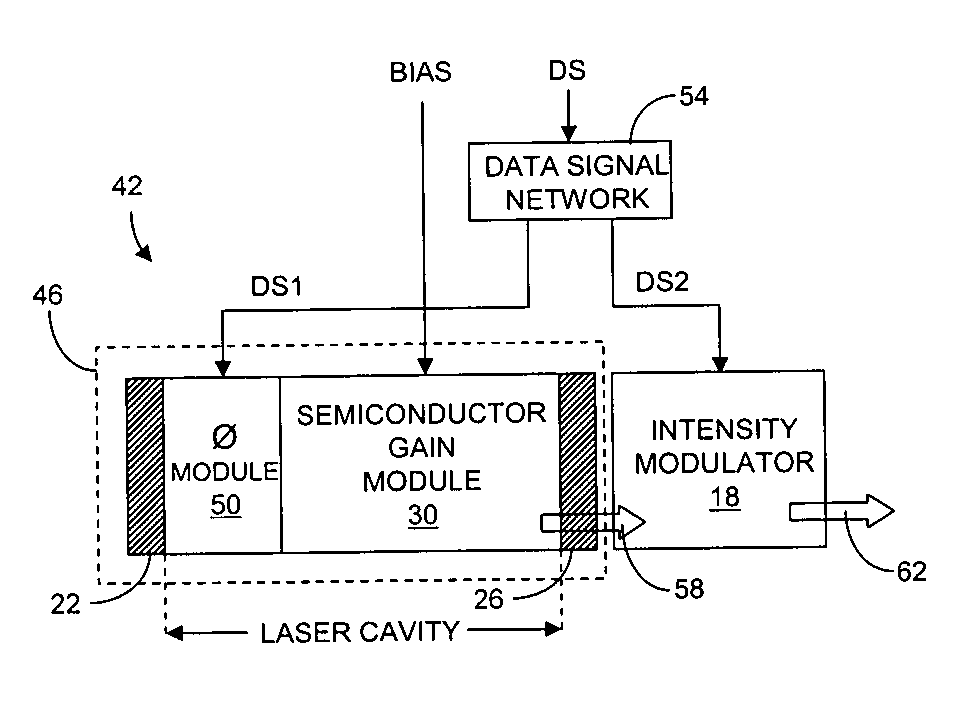
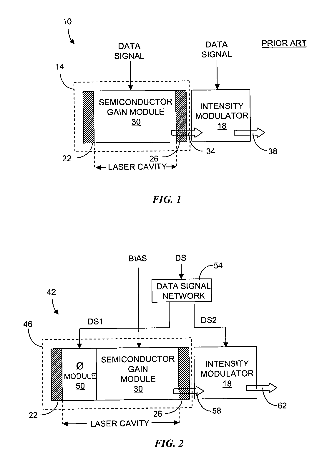
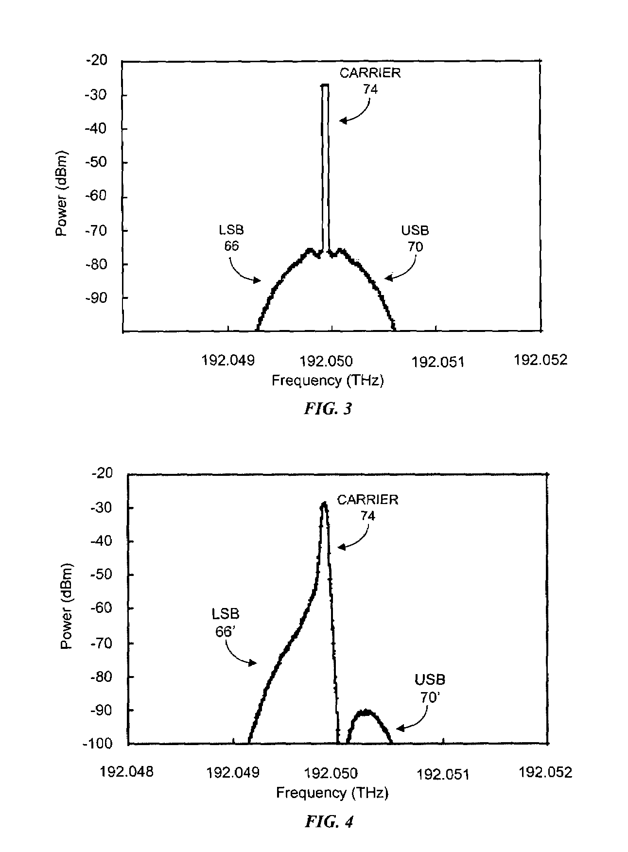
The invention is about a method and apparatus for generating an optical signal with a single sideband (SSB) using a semiconductor laser. The method involves generating a data signal at two power levels, with a predetermined ratio, and applying it to a phase module in a laser cavity to generate a frequency modulated laser signal with a double sideband. The intensity of the laser signal is then modulated based on a second data signal to generate the SSB optical signal. The technical effect of this invention is the generation of a high-quality optical signal with reduced sideband noise, which is useful in optical communication systems.

Problems solved by technology

High data rate optical communication systems are subject to the effects of chromatic dispersion.
It can be difficult to upgrade a communications network because of the variety of communication path lengths possible between optical sources and receivers.
Moreover, dispersion compensation equipment represents a considerable expense and can result in an optical loss that may not be acceptable for high bit rate systems.
However, such systems are typically expensive and require complex feedback systems.
However, the current modulated data signal according to this technique also imparts an unwanted intensity modulation to the laser output beam emitted by the semiconductor laser, resulting in incomplete cancellation of one sideband.
Consequently, the performance of optical communications systems employing transmitters using this technique is limited.

Method used


Image

  • Single sideband optical transmitter
  • Single sideband optical transmitter
  • Single sideband optical transmitter

Examples


Embodiment Construction

[0015]In brief overview the present invention relates to an optical transmitter for generating an SSB optical signal. A semiconductor laser and an intensity modulator are integrated in a single transmitter device. The semiconductor laser includes an integral phase module for generating a frequency modulated optical signal. The SSB optical transmitter of the invention has fewer components than other transmitters used to generate SSB optical signals and, therefore, has an increased manufacturing yield and reliability, a lower fabrication cost and a decreased size. Communication networks can be upgraded for higher data rates by replacing existing optical sources with the SSB optical transmitter of the invention without the need to modify or replace other physical infrastructure. Moreover, the maximum allowable distance between the optical source and its receiver can be more than doubled and in some instances can exceed the maximum allowable distance of DSB optical transmitters by a fac...


PUM

PropertyMeasurementUnit
power levelaaaaaaaaaa
poweraaaaaaaaaa
phaseaaaaaaaaaa

Abstract

Described are an optical transmitter and a method for generating a single sideband optical signal. The method includes generating a data signal at a first power level and at a second power level with a predetermined ratio being defined between the power levels. The data signal at the first power level is applied to a phase module disposed in a laser cavity of a semiconductor laser to generate a frequency modulated laser signal having a double sideband. The intensity of the frequency modulated laser signal is modulated in response to the data signal at the second power level to yield the single sideband optical signal. Optical transmitters implementing the method have an increased manufacturing yield and reliability, a lower fabrication cost and a decreased size compared to other optical single sideband optical transmitters.

Description

GOVERNMENT RIGHTS IN THE INVENTION[0001]This invention was made with United States government support under Contract No. F19628-00-C-0002 awarded by the Defense Advanced Research Project Agency. The government may have certain rights in the invention.FIELD OF THE INVENTION[0002]The invention relates generally to optical communications. More particularly, the invention relates to single sideband optical transmitters for long distance optical communications.BACKGROUND OF THE INVENTION[0003]High data rate optical communication systems are subject to the effects of chromatic dispersion. Over long distances, compensation is necessary to support a predetermined bandwidth and bit error rate. Various techniques have been used to reduce the effects of chromatic dispersion. One common technique employs one or more dispersion compensating optical fibers to compensate for the chromatic dispersion resulting from transmission through a communication optical fiber. The length of dispersion compens...

Claims


Application Information

Patent Timeline
Patent Type & Authority Patents(United States)
IPC IPC(8): H04B10/04G02B26/00G02F1/00H01S3/10H04B10/12
CPCH04B10/504H04B10/505H04B10/5165
Inventor SCHULZ, PETER A.DONOVAN, PAULA J.HENION, SCOTT
Owner MASSACHUSETTS INST OF TECH
Learn More