Aircraft fuselage element and method of taking a number of pictures

a technology of which is applied in the field of aircraft fuselage element and number of pictures, can solve the problems of high level of manufacturing expenditure for glass dome, high level of acceleration, and the movement of optical distortion phenomena in pictures taken, so as to achieve simple control, the effect of reducing the cost of moving the fuselage body and reducing the cost of production

Inactive Publication Date: 2008-01-29
BODENSEEWERK GERATETECHNIK GMBH
View PDF16 Cites 14 Cited by
  • Summary
  • Abstract
  • Description
  • Claims
  • Application Information

AI Technical Summary

Benefits of technology

[0012]A further advantage of the invention is attained by at least two viewing windows which are mounted rotatably about a common axis of rotation. It is possible for a camera to take pictures successively through the two viewing windows, whereby it is possible to avoid follower tracking movement of the viewing window with a large pivotal movement of the camera or an optical element of the camera. It is also possible for two cameras to take pictures through the two viewing windows at the same time.
[0013]In particular for taking high-resolution pictures the viewing window desirably includes a plane-parallel viewing pane. That makes it possible to achieve a substantially distortion-free view through the viewing window.
[0014]The invention further proposes an optical system with an aircraft fuselage element as described hereinbefore, which includes an optical element arranged in the internal cavity. High-resolution pictures can be taken in a substantially distortion-free fashion through the movable viewing window, by means of the optical element. The system serves to take pictures of the surroundings of the system, in which respect the optical element can be a camera, a lens or a mirror. If the internal cavity is arranged to project at least partially beyond the surrounding outside fuselage casing of the aircraft, that makes it possible to enjoy a panoramic view on the part of the optical element through the viewing window.
[0015]The optical element is advantageously mounted rotatably independently of the fuselage body. That can provide for simple control for the movement of the fuselage body and the expenditure and complication in terms of moving the fuselage body can be kept low. A high level of acceleration of a possibly light optical element can be decoupled from acceleration of the fuselage body. In particular, the fuselage body is mounted rotatably about a first axis and the optical element is mounted rotatably about a second axis which is movable independently of the first axis. The mounting arrangement for the fuselage body can remain simple, in regard to a demanding movement on the part of the optical element. The optical element for example can be cardanically supported.
[0016]A further advantage is achieved if the optical system includes a control device which is adapted to control a movement of the optical element and the fuselage body, with the movements being related to each other. The optical element can be caused to track a movement of the viewing window and vice-versa without that involving particular mechanical complication and expenditure.
[0017]Desirably the control device is adapted for continuous rotation of the fuselage body with simultaneous stepwise rotation of the optical element. The possibly heavy fuselage body can in that way be moved at a low level of acceleration, in particular uniformly, while the optical element can come to a stop to take a picture. While the picture is being taken the fuselage body continues to rotate. In that arrangement the viewing window is advantageously larger than the entry aperture of the optical element.

Problems solved by technology

That relative movement results in the movements of optical distortion phenomena in the pictures taken, which can only be eliminated with very great difficulty.
The disadvantage of the optical distortion phenomena and the high level of manufacturing expenditure for a glass dome can be obviated by a viewing window comprising a number of plane-parallel individual panes, whereby a panoramic view for the camera apparatus is also achieved.
The transitions between the individual panes however inevitably give rise to optical loss due to shadowing and pupil division.
If the number of individual panes is reduced then the size of the individual panes increases and the angle of incidence of the radiation becomes correspondingly greater, in which respect a problem in terms of reflection compensation occurs, in particular in the case of a camera apparatus for use in the infrared range.
In addition the technical expenditure involved in producing a facet window with infrared transmission for an optical system designed at the diffraction limit is considerable.

Method used


Image

  • Aircraft fuselage element and method of taking a number of pictures
  • Aircraft fuselage element and method of taking a number of pictures
  • Aircraft fuselage element and method of taking a number of pictures

Examples


Embodiment Construction

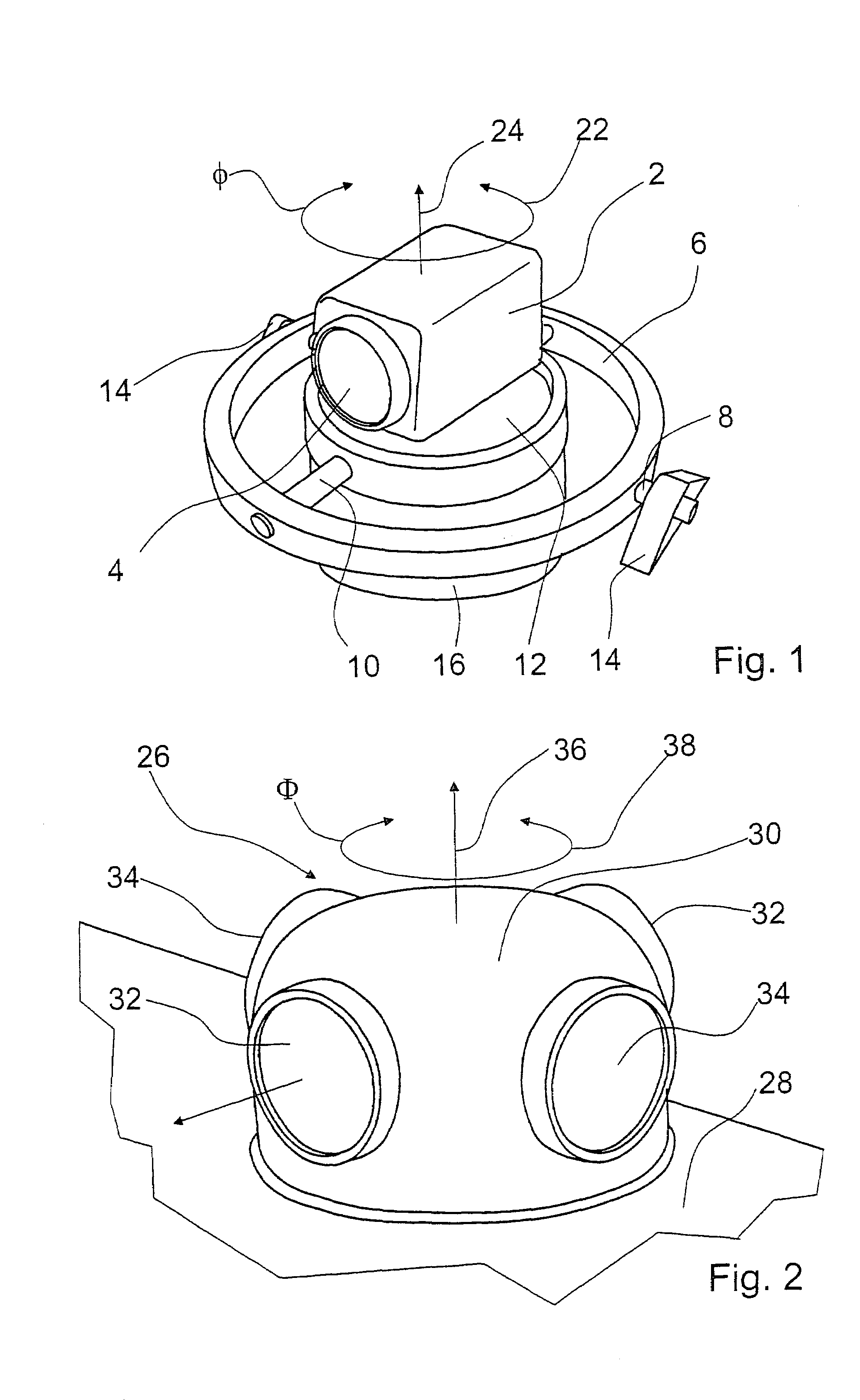
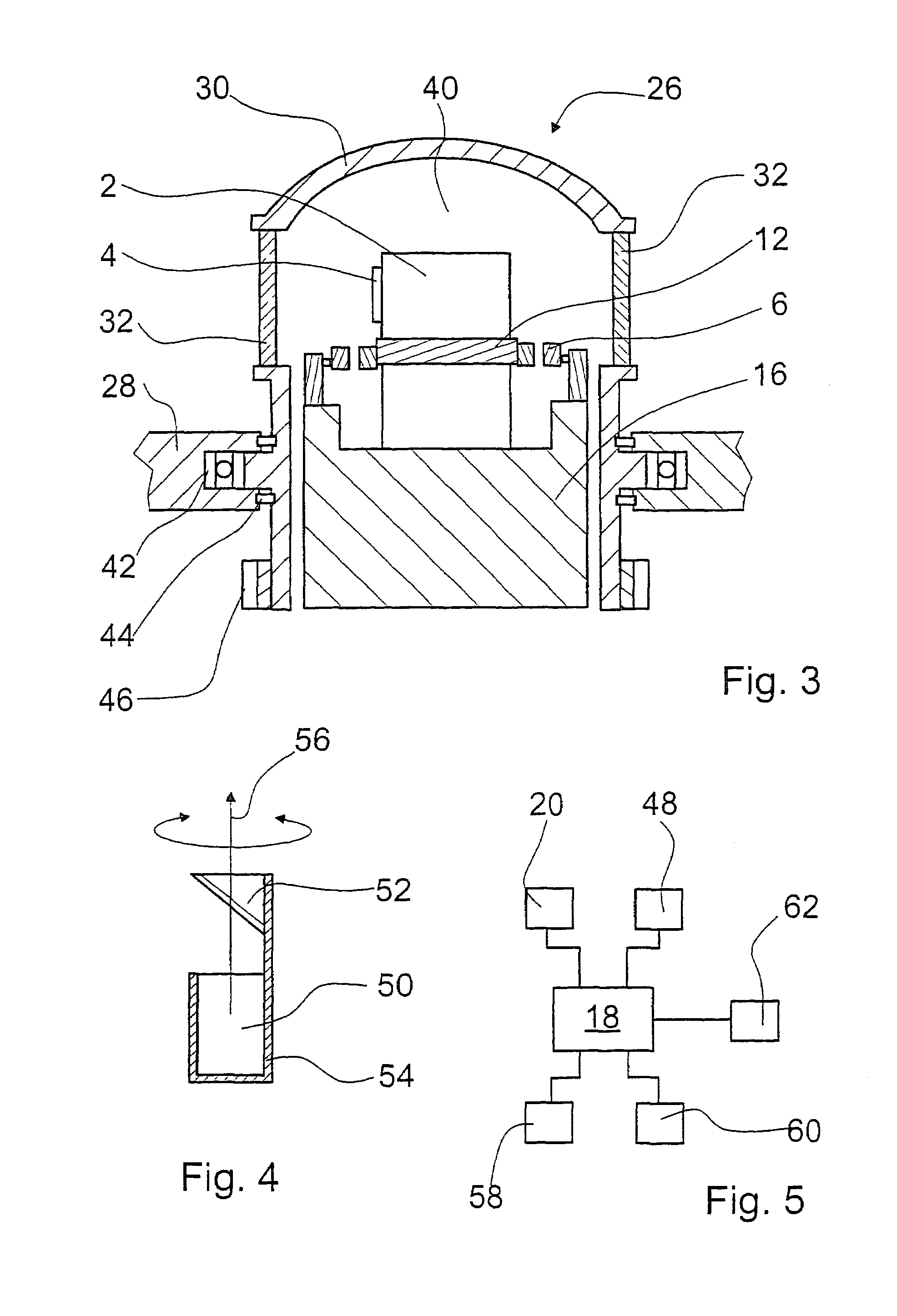
[0031]FIG. 1 shows a camera apparatus 2 for taking pictures through an optical element 4 in the form of a lens. The camera apparatus 2 is mounted in a cardanic frame system 6 which includes two axes of rotation 8, 10 which are arranged in mutually perpendicular relationship and which two-dimensionally rotatably hold a turntable 12. The camera apparatus 2 is fixed on the turntable 12. The frame system 6 is fixed by means of two fixing elements 14 in an aircraft (not shown). The turntable 12 is connected to a movement device 16 which is movable by means of a control device 18 (FIG. 5) and a motor drive 20. The turntable 12 is mounted in such a way that it can be decoupled from minor movements of the aircraft. In addition the turntable 12 is rotatable completely about an axis of rotation 24 in one direction 22 of rotation.

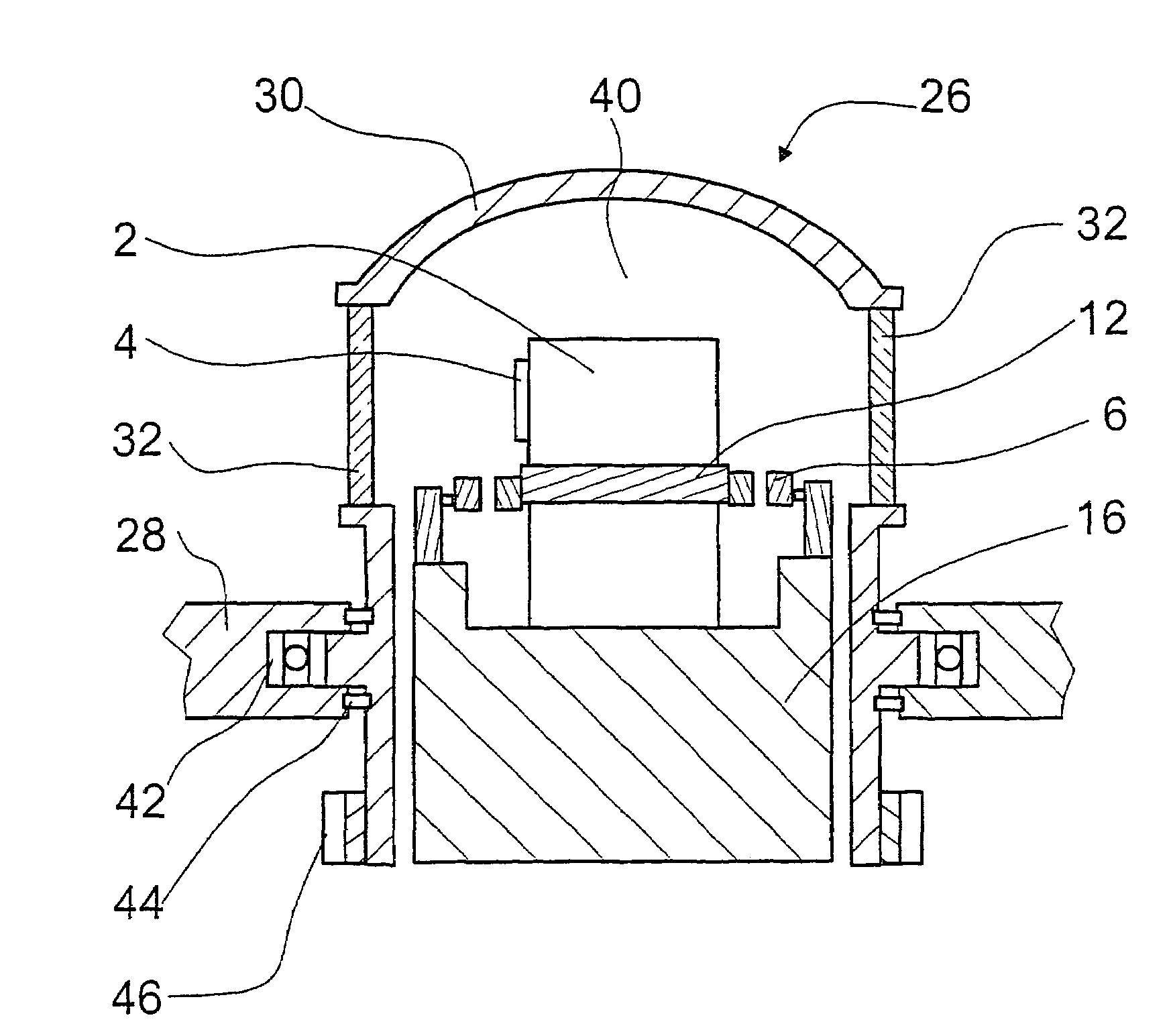
[0032]FIG. 2 shows an aircraft fuselage or casing element 26 which projects out of a surrounding aircraft fuselage segment 28. The aircraft fuselage element 26 includ...


PUM


Abstract

An aircraft fuselage element (26) with a fuselage body (30) which forms an internal cavity (40) and which includes a viewing window (32, 34). To provide for taking substantially distortion-free high-resolution pictures in the infrared wavelength range and from a large angular range the fuselage body (30) is mounted for rotation about an axis of rotation (36).

Description

BACKGROUND OF THE INVENTION[0001]1. Field of the Invention[0002]The invention concerns an aircraft fuselage element with a fuselage body which forms an internal cavity and which includes a viewing window. The invention further concerns a method of taking a number of pictures of the surroundings of a camera apparatus, in which an optical element is moved into a starting position, a picture is taken through a viewing window of an aircraft fuselage element at least partially surrounding the optical element, the optical element is moved into a new position and a new picture is taken through the viewing window.[0003]2. Discussion of the Prior Art[0004]To take pictures from the surroundings of an aircraft, for example for the purposes of cartography of the surroundings, it is known for pictures to be taken through a viewing window in the aircraft fuselage. If wide-angle pictures of the surroundings or a number of pictures around the aircraft are to be taken, consideration is given to moun...

Claims


Application Information

Patent Timeline
Patent Type & Authority Patents(United States)
IPC IPC(8): G03B39/00B64C1/00B64C1/36B64D47/08G03B15/00
CPCB64C1/36B64D47/08G03B15/00
Inventor KEMPAS, HAGEN
Owner BODENSEEWERK GERATETECHNIK GMBH
Why Eureka
Try Eureka