Subranging analog to digital converter with multi-phase clock timing
What is Al technical title?
Al technical title is built by PatSnap Al team. It summarizes the technical point description of the patent document.
a digital converter and analog to digital converter technology, applied in the field of analog to digital converters adc, can solve the problems of coarse adc amplifiers, the timing proposed in conventional art has important disadvantages, and the input signal is available for ad
Inactive Publication Date: 2008-01-29
AVAGO TECH INT SALES PTE LTD
View PDF14 Cites 21 Cited by
Summary
Abstract
Description
Claims
Application Information
AI Technical Summary
This helps you quickly interpret patents by identifying the three key elements:
Problems solved by technology
Method used
Benefits of technology
[0012]The present invention is directed to an analog to digital converter that substantially obviates one or more of the problems and disadvantages of the related art.
Problems solved by technology
However, the disadvantage of a T / H is that the sampled input signal is available to the ADC for only half a clock period.
However, the timing proposed in conventional art has important disadvantages.
This leaves much less time available for the coarse ADC amplifiers to amplify the signals and the coarse comparators to decide on a voltage to latch.
Thus, one of the bottlenecks in subranging ADC's is the limited amount of time available for performing the coarse quantization.
Unfortunately, most of these solutions require the use of a S / H, or use time-interleaved ADC's.
This disadvantageously affects the required power and area.
Method used
Image
Click on the blue label to locate the original text in one second.
Reading with bidirectional positioning of images and text.
Examples
Embodiment Construction
[0029]Reference will now be made in detail to the preferred embodiments of the present invention, examples of which are illustrated in the accompanying drawings.
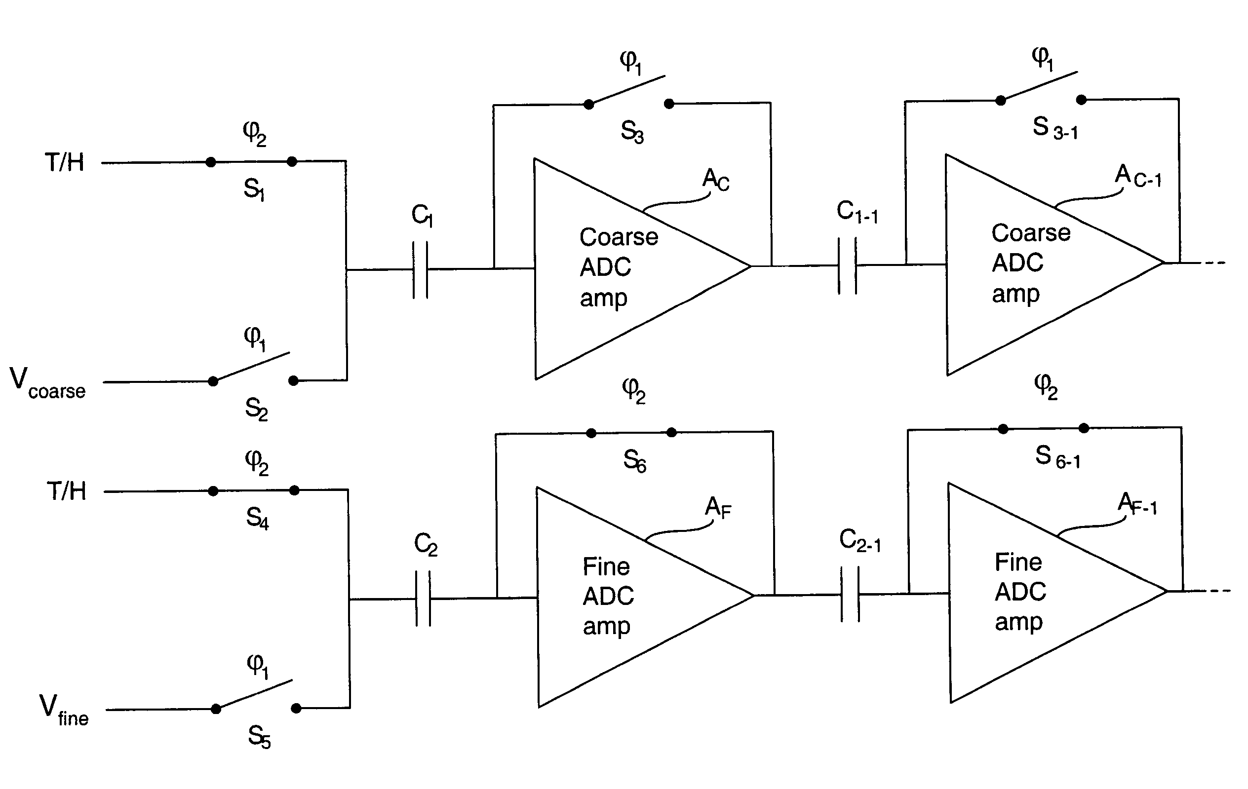
[0030]This disclosure describes a subranging ADC that uses a two-phase clock timing method that permits the use of a T / H instead of a S / H, thus enabling a low-power, low-area implementation on a chip. The timing technique described herein can use a T / H, instead of a S / H, and does not require time-interleaved ADC's in order to realize high-speed operation.
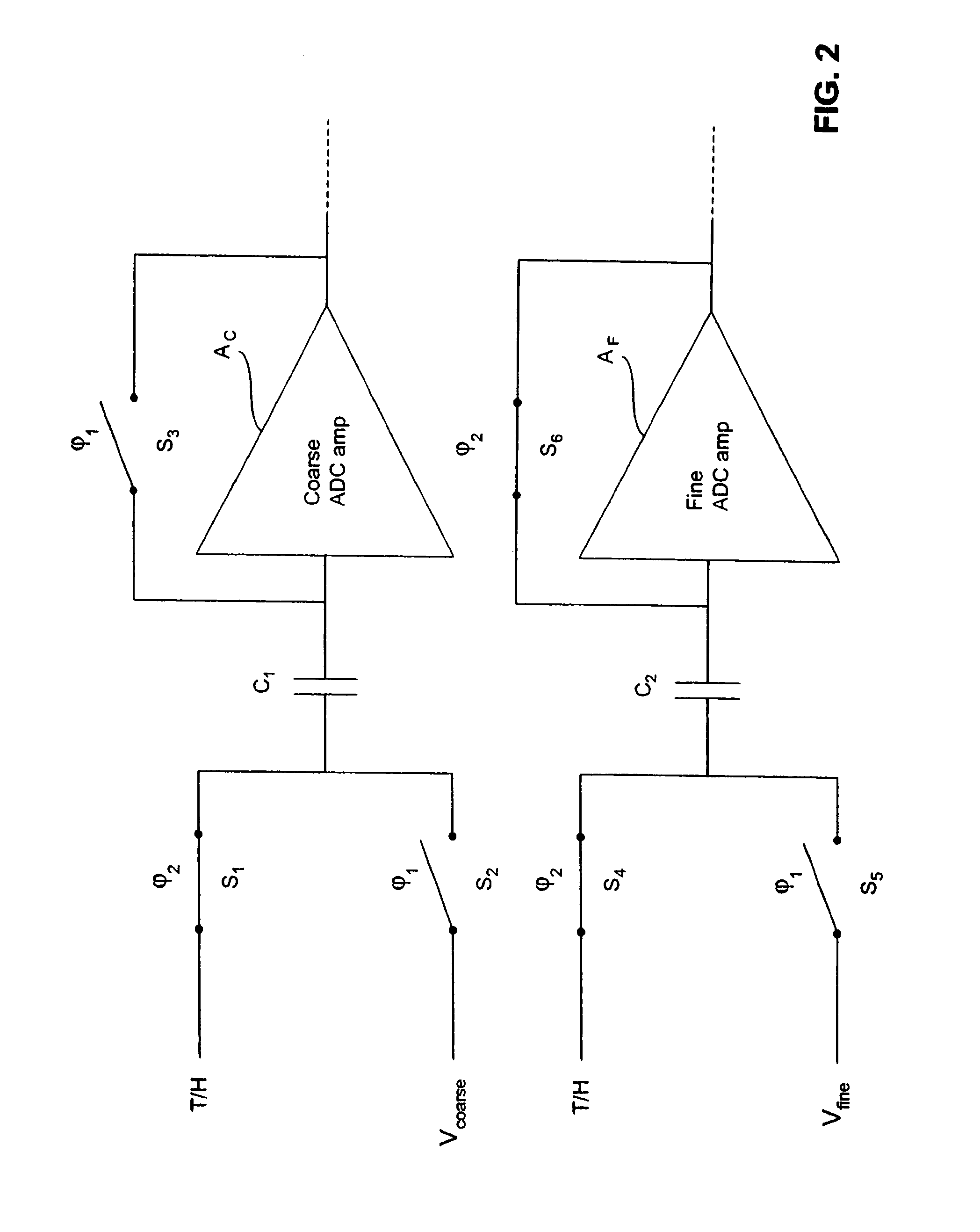
[0031]FIG. 2 shows a single coarse amplifier AC and a single fine amplifier AF that illustrate the proposed timing method of the present invention. Preferably, the coarse amplifier AC and the fine amplifier AF are implemented using auto-zero amplifiers. See, e.g., http: / / www.web-ee.com / primers / files / auto-zero_amps.pdf. for a general discussion of auto-zero amplifiers. (To the extent the overall block diagram of the architecture is the same as that in FIG. 1, the same referen...
PUM
Abstract
An N-bit analog to digital converter includes a reference ladder, a track-and-hold amplifier connected to an input voltage, a coarse ADC amplifier connected to a coarse capacitor at its input and having a coarse ADC reset switch controlled by a first clock phase of a two-phase clock, a fine ADC amplifier connected to a fine capacitor at its input and having a fine ADC reset switch controlled by a second clock phase of the two-phase clock, a switch matrix that selects a voltage subrange from the reference ladder for use by the fine ADC amplifier based on an output of the coarse ADC amplifier, and wherein the coarse capacitor is charged to a coarse reference ladder voltage during the first clock phase and connected to the T/H output during the second clock phase, wherein the fine capacitor is connected to a voltage subrange during the first clock phase and to the T/H output during the second clock phase, and an encoder that converts outputs of the coarse and fine ADC amplifiers to an N-bit output.
Description
CROSS-REFERENCE TO RELATED APPLICATIONS[0001]This application is a continuation of application Ser. No. 10 / 359,201, filed on Feb. 6, 2003 now U.S. Pat. No. 6,653,966, Titled: SUBRANGING ANALOG TO DIGITAL CONVERTER WITH MULTI-PHASE CLOCK TIMING, Inventors: van der Goes et al, which is a continuation of application Ser. No. 10 / 158,773, filed on May 31, 2002 now U.S. Pat. No. 6,583,747 Titled:SUBRANGING ANALOG TO DIGITAL CONVERTER With MULTI-PHASE CLOCK TIMING,Inventors: van der Goes et al., which is a Continuation-in-Part of application Ser. No. 10 / 153,709, Filed: May 24, 2002 now U.S. Pat. No. 6,628,224, Titled: DISTRIBUTED AVERAGING ANALOG TO DIGITAL CONVERTER TOPOLOGY, Inventors: MULDER et al.; and is related to application Ser. No. 10 / 158,774, Filed: May 31, 2002, Titled: ANALOG TO DIGITAL CONVERTER WITH INTERPOLATION OF REFERENCE LADDER, Inventors: MULDER et al; application Ser. No. 10 / 158,595, Filed: May 31, 2002, Titled: HIGH SPEED ANALOG TO DIGITAL CONVERTER, Inventor: Jan MUL...
Claims
Application Information
Patent Timeline
Application Date:The date an application was filed.
Publication Date:The date a patent or application was officially published.
First Publication Date:The earliest publication date of a patent with the same application number.
Issue Date:Publication date of the patent grant document.
PCT Entry Date:The Entry date of PCT National Phase.
Estimated Expiry Date:The statutory expiry date of a patent right according to the Patent Law, and it is the longest term of protection that the patent right can achieve without the termination of the patent right due to other reasons(Term extension factor has been taken into account ).
Invalid Date:Actual expiry date is based on effective date or publication date of legal transaction data of invalid patent.