
Cross-phase adapter for powerline communications (PLC) network

a technology of powerline communication and cross-phase adapters, applied in powerline communication applications, instruments, electric controllers, etc., can solve the problem of significant reduction of network bandwidth, and achieve the effect of reducing the effect of cross-phase communication

Active Publication Date: 2008-01-29
SONY CORP +1
View PDF13 Cites 31 Cited by
  • Summary
  • Abstract
  • Description
  • Claims
  • Application Information

AI Technical Summary

Benefits of technology

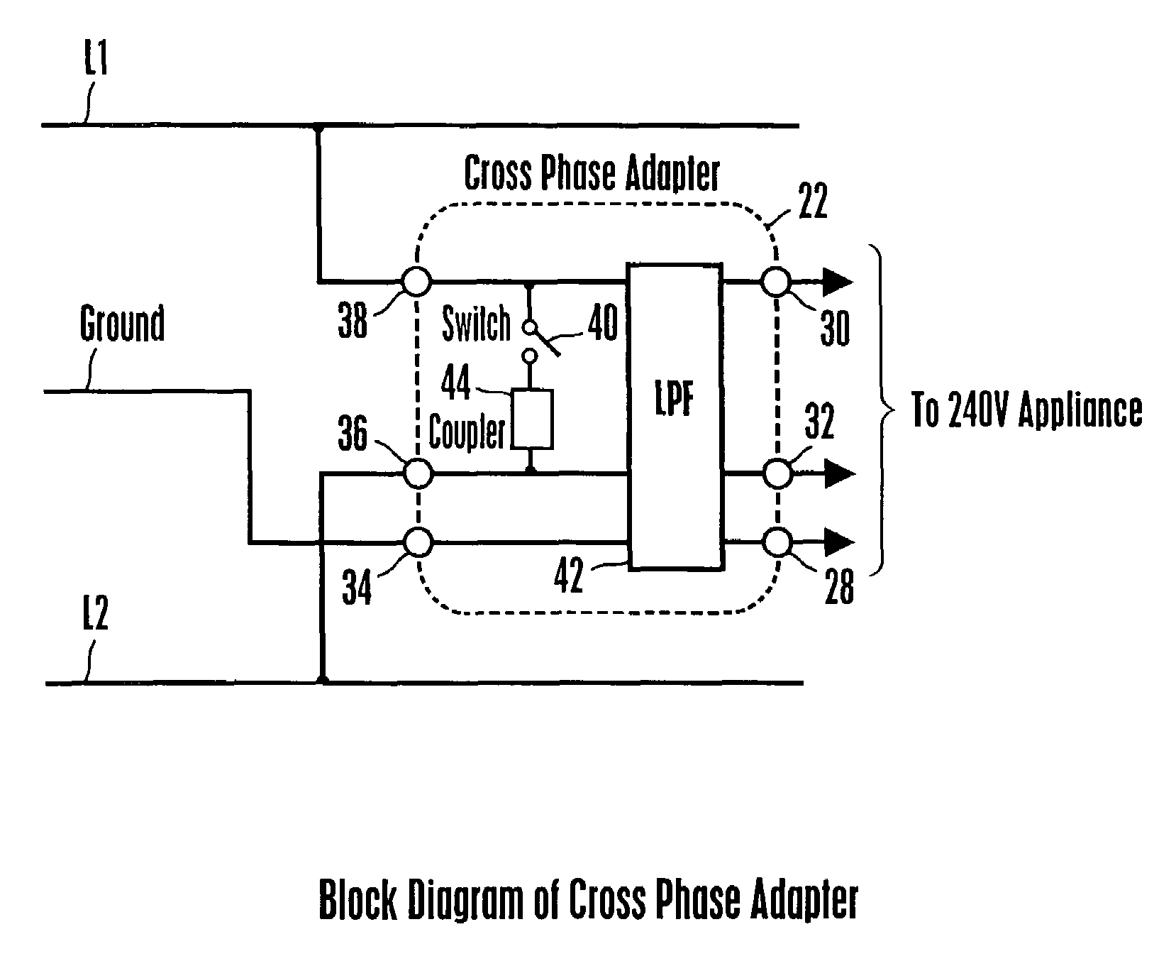
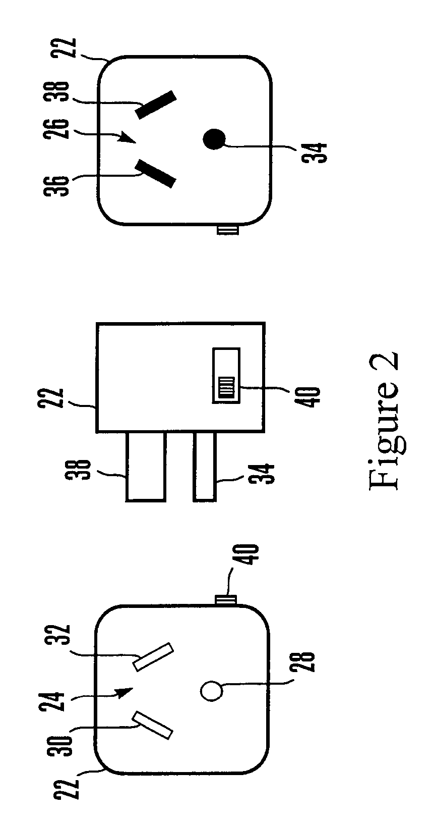
[0007]In another aspect, an adapter includes a housing, a 240 volt plug on the housing, and a 240 volt socket on the housing. A neutral pathway is in the housing, as is an L1 line pathway and an L2 line pathway. The three pathways extend between the plug and the socket. A coupling device interconnects the L1 line pathway and the L2 line pathway to reduce the effects of cross phase communication between a PLC transmitter and a PLC receiver.

Problems solved by technology

This undesirable outcome significantly reduces network bandwidth.

Method used


Image

  • Cross-phase adapter for powerline communications (PLC) network
  • Cross-phase adapter for powerline communications (PLC) network
  • Cross-phase adapter for powerline communications (PLC) network

Examples


Embodiment Construction

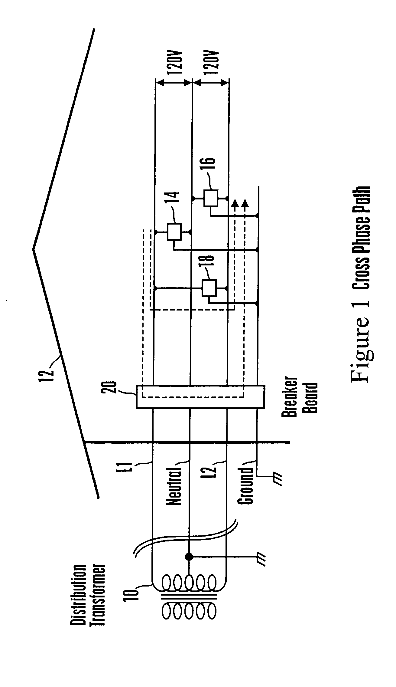
[0013]Referring initially to FIG. 1, a home entertainment system is shown to illustrate an environment in which the present cross-phase adaptor can be used. A distribution transformer 10 provides power to a structure 12, with the structure 12 having a power grid including a neutral line generally at ground potential, an L1 line that is at a 120 volt potential relative to neutral, and an L2 line that likewise is at a 120 volt potential relative to neutral, with 240 volt s of potential existing between the lines L1, L2.

[0014]Accordingly, 120 volt devices 14, 16 can be plugged into respective 120 volt sockets connected to neutral and to one of the L1 or L2 lines, whereas a 240-volt appliance 18, for example, a laundry dryer can be plugged into a 240 volt socket that is connected across both the L1 and L2 lines as figuratively shown. As recognized above, when both of the transmitter and the receiver in a home entertainment network are plugged into sockets on the same line (L1 or L2), no...


PUM


Abstract

An adapter to reduce the effects of cross phase communication between a PLC transmitter plugged into one of the L1 or L2 power lines of a home and a PLC receiver plugged into the opposite L2 or L1 power line includes a housing with one side configured as a 240 volt plug and an opposite side configured as a 240 volt, so that the adapter can be plugged into a 240 volt wall socket and a 240 volt appliance plugged into the adapter. A coupler or a repeater is in the adapter and extends between the L1 and L2 lines to reduce attenuation of a communication signal from the transmitter or alternatively to amplify the signal and send it on to the receiver. A high frequency filter can be interposed between the coupler and the 240 volt appliance to prevent noise from the appliance from entering the communication signal and for preventing communication signals from entering the appliance.

Description

FIELD OF THE INVENTION[0001]The present invention relates generally to home entertainment systems.BACKGROUND OF THE INVENTION[0002]Home entertainment systems have been provided that can include a set-top box media server that communicates with various components in the home, e.g., TVs, laptop computers, and custom display devices. To establish network communication paths, power line communication (PLC) networks have been introduced and have gained in popularity owing to the fact that the home's existing AC power grid is used to also carry entertainment data between various components in the home entertainment system which are plugged into AC wall sockets. In this way, no new wiring is required, rendering most home power grids into effective network backbones.[0003]The present invention makes the following critical observation. Most U.S. homes use a single-phase three-line electricity system in which three lines (L1 and L2“hot” lines at 120 volts each, plus a neutral line) are provid...

Claims


Application Information

Patent Timeline
Patent Type & Authority Patents(United States)
IPC IPC(8): H04M11/04
CPCH04B3/56H04B2203/5454H02J13/00009
Inventor IWAMURA, RYUICHI
Owner SONY CORP
Learn More