Angioplasty device and method of making same

a technology of an angioplasty device and a method of making it, which is applied in the direction of blood vessels, prostheses, catheters, etc., can solve the problems of emboli, stroke, clots, and clots, and achieve the effect of increasing suction, reducing bleeding, and maximizing suction

Inactive Publication Date: 2008-01-29
K HEART IND
View PDF49 Cites 49 Cited by
  • Summary
  • Abstract
  • Description
  • Claims
  • Application Information

AI Technical Summary

Benefits of technology

[0029]One feature and advantage of the present invention is that it can provide a small diameter angioplasty device that can trap and remove substantially all physiologically significant particles. Another feature and advantage of the present invention is that it can provide aspiration, blocking, and capturing capabilities in a single catheter. Yet another feature and advantage is that the present invention maximizes the amount of suction per unit size, thus providing the doctor with more suction in larger vessels than presently available. These and other features, aspects, and advantages of the present invention will become bette

Problems solved by technology

Many problems have been associated with these angioplasty devices.
Perhaps the most significant problem is the creation of particulate matter during the obstruction removal procedure.
These particles are released into the fluid flowing through the vessel and can lead to emboli, clots, stroke, heart failure, hypertension and decreased renal function, acute renal failure, livedo reticularis and gangrene of the lower extremities, abdominal pain and pancreatitis, cerebral infarction and retinal emboli, tissue injury, tissue death, emergency bypass surgery, death and other undesirable side effects and complications.
Even very small particles can cause significant harm.
Furthermore, in the case of the heart, approximately 45% of the capillaries are closed at any given time, so that any particle, no matter how small, dislodged into this organ is liable to capture.
Accordingly, it has become apparent that distal embolization presents a formidable threat.
One problem with this design, however, is that it is difficult to simultaneously provide an angioplas

Method used


Image

  • Angioplasty device and method of making same
  • Angioplasty device and method of making same
  • Angioplasty device and method of making same

Examples


embodiment 120

[0139]In operation, the valve embodiment 120 is actuated by longitudinally moving the guidewire 44 relative to the catheter wall 48. That is, pulling the guidewire 44 in a proximal direction relative to the catheter wall 48 causes the generally planar engagement surface 126 to sealably engage the abutment 121, which prevents fluid from flowing through the circular flow channel 128. Pushing the guidewire 44 in a distal direction relative to the catheter wall 48 causes the stopper 122 to disengage from the abutment 121, which allows fluid to flow through the circular flow channel 128.

[0140]Other valve embodiments 120 capable of being actuated by longitudinal motion are also within the scope of the present invention. For example, the stopper 122 may be rotated 180 degrees so that the conically shaped surface 124 engages the abutment 121, rather than the generally planar engagement surface 126. These embodiments may be desirable because the conically shaped surface 124 will self-center ...

embodiment 38

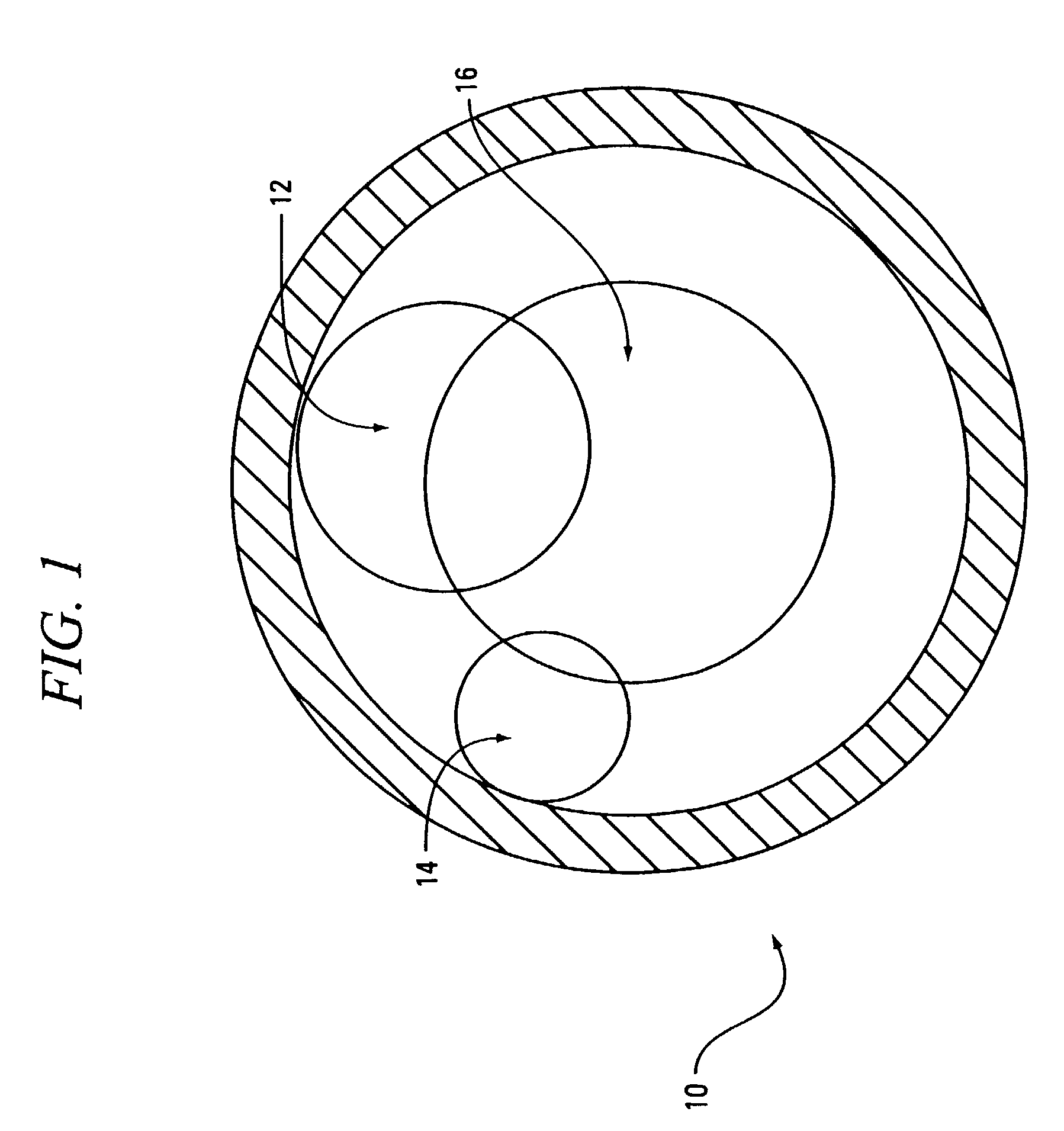
[0151]FIG. 19 is a sectional view of an angioplasty device embodiment having a coupling device 190 with four radially spaced sockets 189. FIG. 20 is a sectional view of the coupling device 190. The coupling device 190 in this embodiment may be any device that prevents the balloon catheter 102 from rotating relative to the trap catheter bundle 100 (or translating, if used with the trap embodiment 38 described with reference to FIGS. 21 and 22). These embodiments are desirable because the trap catheter bundle 100 and the balloon catheter bundle 102 may be manufactured separately, then combined as needed. FIG. 27 depicts an alternate embodiment in which a second group of struts 49a connect the coupling device 190 to an end 191 of the trap catheter bundle 100. In operation, the trap catheter bundles 100 in FIGS. 19 and 27 may be inserted over an in-place balloon catheter 102 and then either removed along with the balloon catheter 102 or by itself, depending on the configuration of the c...

embodiment 100

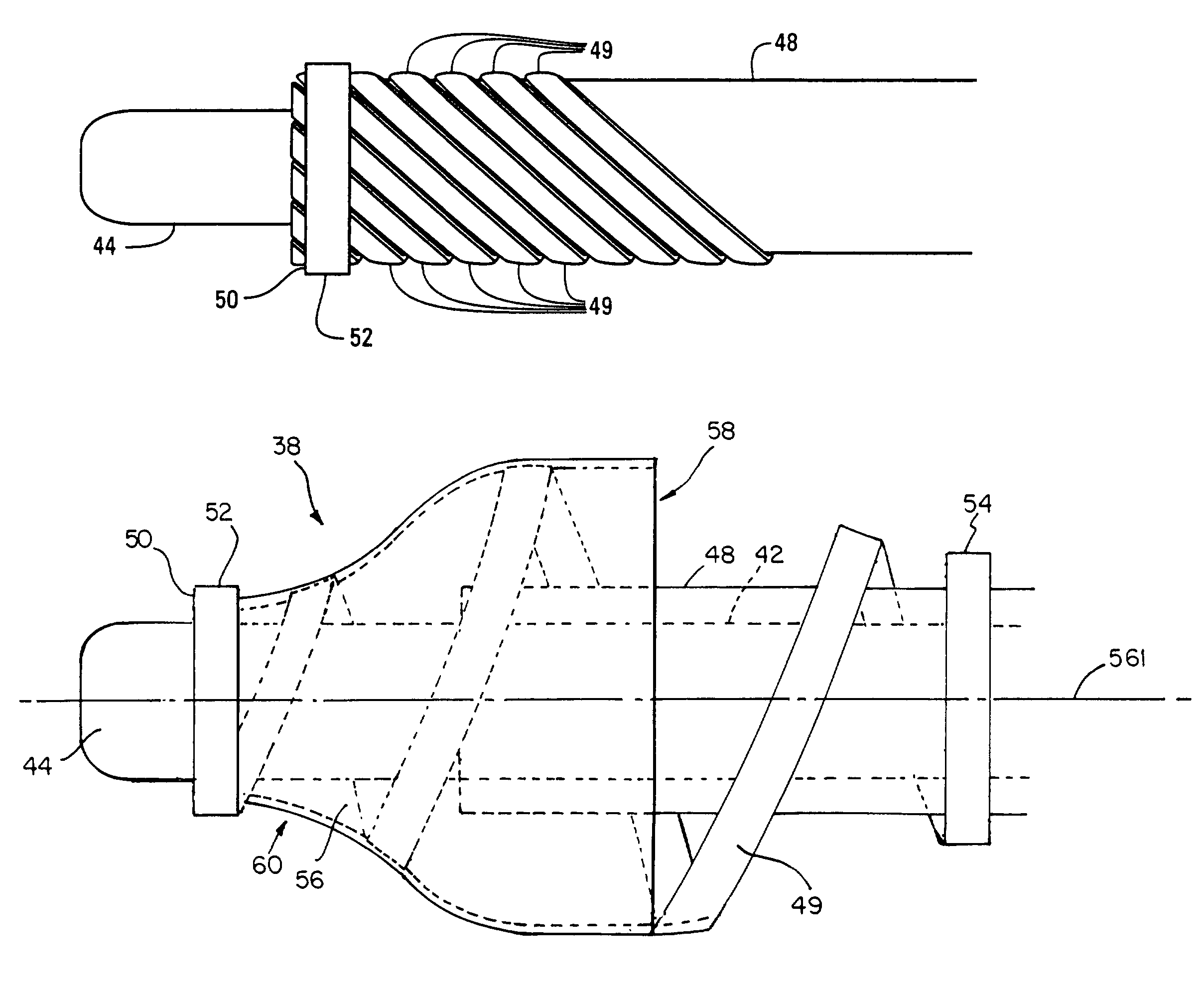
[0152]FIGS. 21 and 22 are sectional views of another trap catheter bundle embodiment 100, in which the trap 38 is actuated by a translation between the guidewire 44 and the catheter wall 148. In this embodiment, a first end 180 of the struts 49 is connected to the guidewire 44 and a second end 182 of the struts 49 is attached to the catheter wall 148. Translating the guidewire 44 (i.e., moving the guidewire in an axial direction) relative to the catheter wall 148 biases the first end 180 away from the end 182. This, in turn, actuates the struts 49 between an arcuately expanded position, such as that shown in FIG. 21, and a contracted position, such as that shown in FIG. 22. Accordingly, the struts 49 in this embodiment remain generally parallel to the guidewire 44 throughout the procedure. Those skilled in the art will recognize that this actuation mechanism also could be used with the embodiments described with reference to FIGS. 1-20.

[0153]FIGS. 23A-24B are sectional views of two ...


PUM


Abstract

An angioplasty device and particle trap for use in removal of a particle from a small diameter vessel or vessel-like structure is disclosed. One embodiment includes a catheter for insertion into a vessel-like structure, the catheter having a catheter wall and a movable member, a trap operably connected to the catheter wall and to the movable member, wherein relative motion between the catheter wall and the movable member actuates the trap. In one embodiment, the expanded trap is formed from struts in a spiral-shaped configuration. In one embodiment, the contracted trap forms a waist to creates a pinch-point to trap particles. In one embodiment, the contracted trap forms a cocoon-like structure to further trap particles. In one embodiment, the angioplasty device includes a handle to actuate the trap from a contracted position to an expanded position and return to a contracted position. The handle provides rotational or longitudinal or both types of movement to actuate the trap.

Description

CROSS-REFERENCE TO RELATED APPLICATION(S)[0001]This application is a continuation-in-part of U.S. patent application Ser. No. 09 / 718,732, filed Nov. 22, 2000 now abandoned which is a continuation-in-part of U.S. patent application Ser. No. 09 / 495,833, filed Feb. 1, 2000 now U.S. Pat. No. 6,443,926, both of which are herein incorporated by reference.TECHNICAL FIELD[0002]This invention relates to an angioplasty device for compressing and / or removing atherosclerotic plaques, thromboses, stenoses, occlusions, clots, potential embolic material and so forth (hereinafter “obstructions”) from veins, arteries, vessels, ducts and the like (hereinafter “vessels”). More particularly, the invention relates to a total capture angioplasty device and trap capable of use in small and large diameter vessels and vessel-like structures.BACKGROUND OF THE INVENTION[0003]Angioplasty devices are used to treat a wide variety of conditions and to perform a wide variety of procedures, including without limita...

Claims


Application Information

Patent Timeline
IPC IPC(8): A61M29/00A61B17/22A61F2/01A61F2/06A61M25/00A61M25/10A61M29/02
CPCA61B17/22032A61B17/221A61M25/0029A61M25/0082A61M25/1011A61M25/104A61B2017/00526A61B2017/22001A61B2017/22051A61B2017/2212A61F2/013A61F2/848A61F2002/8483A61M25/0074A61M25/1002A61M25/1006A61M29/02A61M2025/0039A61M2025/004A61M2025/0079A61M2025/091A61M2025/09125A61M2025/1015A61M2025/109A61M2025/1093
Inventor KLETSCHKA, HAROLD D.PACKARD, BRIAN
Owner K HEART IND
Why Eureka
Try Eureka