
Ventilator

a technology of ventilator and air intake, which is applied in the field of ventilator, can solve the problems of difficult mounting, increased construction cost, and bulky ventilator, and achieve the effects of reducing pressure loss and noise, reducing construction cost, and reducing installation difficulty

Inactive Publication Date: 2008-01-29
LG ELECTRONICS INC
View PDF16 Cites 12 Cited by
  • Summary
  • Abstract
  • Description
  • Claims
  • Application Information

AI Technical Summary

Benefits of technology

The compact design reduces installation complexity and costs, minimizes pressure loss and noise, and enhances heat recovery efficiency, allowing for easier mounting on various building structures while maintaining effective air exchange.

Problems solved by technology

The ventilator is bulky due to units built therein, such as fan.
According to this, because the higher storys are required, a construction cost is increased substantially.
Moreover, when it is intended to mount the ventilator on a window or a wall, the mounting is difficult because of the bulk and complicate flow passages.

Method used


Image

  • Ventilator
  • Ventilator
  • Ventilator

Examples


Embodiment Construction

[0044]Reference will now be made in detail to the preferred embodiments of the present invention, examples of which are illustrated in the accompanying drawings. Wherever possible, the same reference numbers will be used throughout the drawings to refer to the same or like parts.

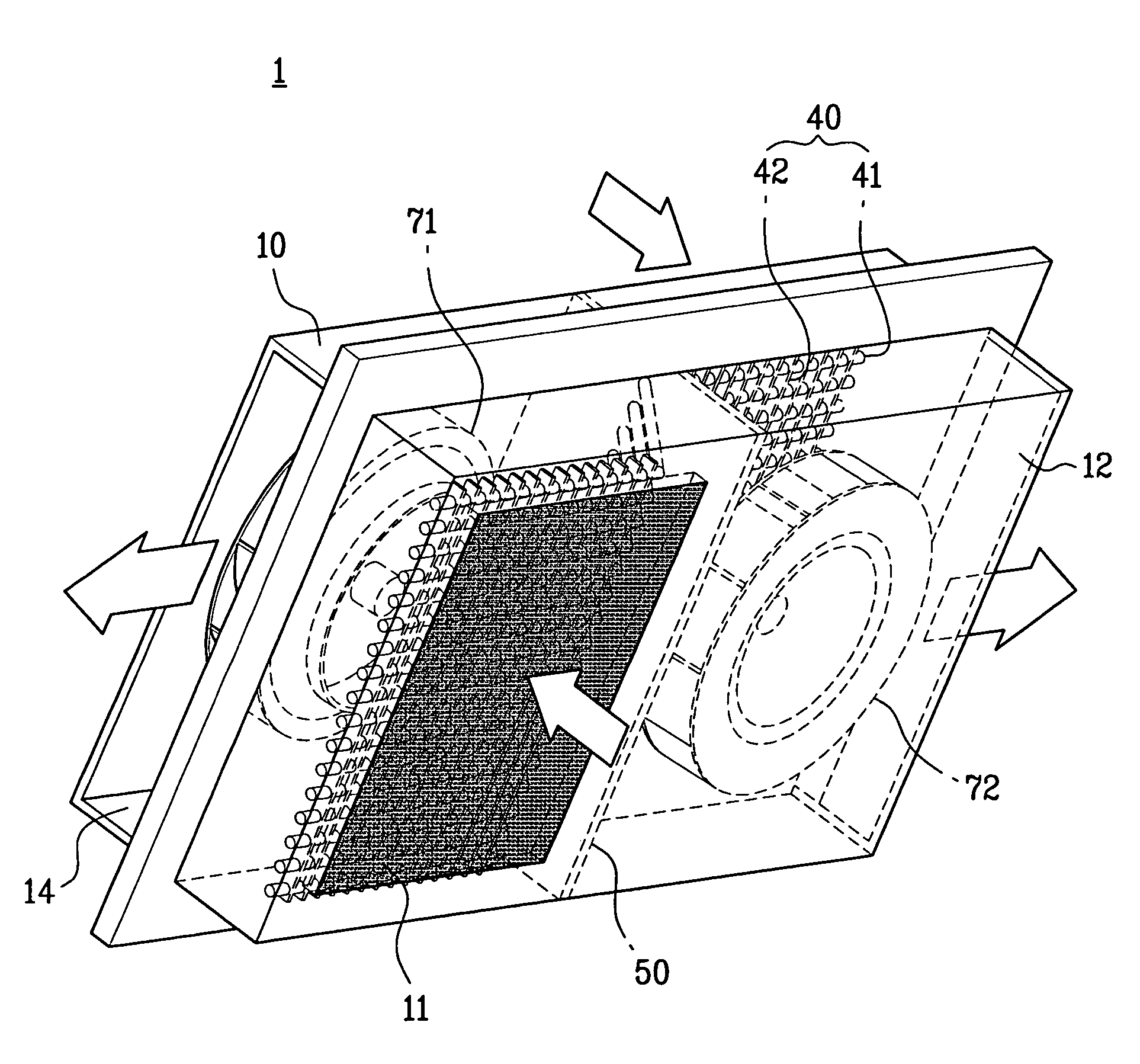
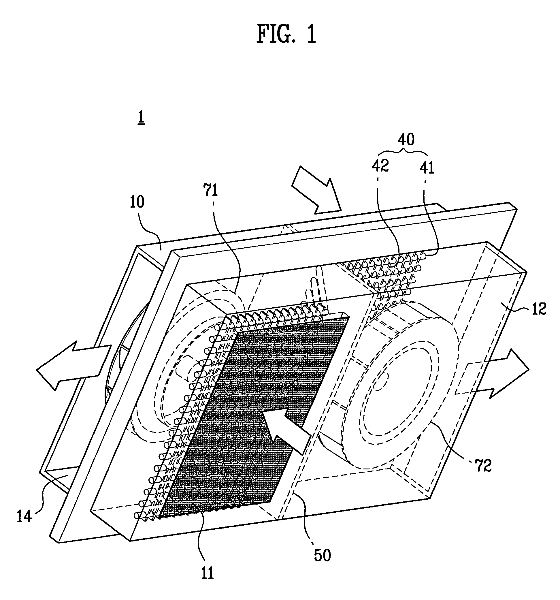
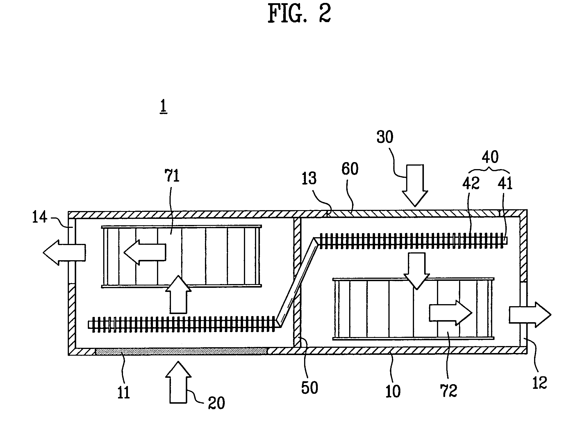
[0045]Referring to FIGS. 1 and 2, the ventilator includes a case 10, fans 71, and 72, and a heat exchanger 40.

[0046]The case 10 forms an exterior, and is mounted on a ceiling or a window of a building. The case 10 has a first flow passage 20 and a second flow passage 30 formed therein. The first flow passage 20 guides room air to an outside of the room, and the second flow passage 30 guides an outdoor air to the room.

[0047]In order to fabricate a compact ventilator 1, the first flow passage 20 is deflected within the case 10 for making a flow direction of the air introduced into the case different from a flow direction of the air discharged to an outside of the room, and the second flow passage 30 is also de...


PUM


Abstract

Ventilator including a case having a first flow passage and a second flow passage therein, at least one fan in the case for supplying room air to a room through the first flow passage, and guiding outdoor air to the room through the second flow passage, and a heat exchanger in the case, the heat exchanger having a working fluid therein for repeating evaporation (heat absorption) and condensing (heat dissipation) by a temperature difference of the air flowing through the first flow passage and the second flow passage, for making the air flowing through the first flow passage and the air flowing through the second flow passage to heat exchange, thereby providing a ventilator which is thin, can be installed conveniently, and can recover a thermal energy from room air, and reduce a pressure loss and noise.

Description

CROSS-REFERENCE TO RELATED APPLICATIONS[0001]This application claims the benefit of Korean Application No. P2004-37801 filed on May 27, 2004, which is hereby incorporated by reference as if fully set forth herein.BACKGROUND OF THE INVENTION[0002]1. Field of the Invention[0003]The present invention relates to ventilators, and more particularly, to a ventilator which is thin, can be installed conveniently, and can recover a thermal energy from room air, and reduce a pressure loss and noise.[0004]2. Discussion of the Related Art[0005]In general, the ventilator discharges room air to an outside of a room, and supplies outdoor air to the room. The ventilator is essential for a building, and mounted on a ceiling or a wall. The ventilator is in communication with the outside of the room through ducts in the ceiling or the wall.[0006]The ventilator is bulky due to units built therein, such as fan. In order to install the ventilator on each of storys of a building, higher storys are required...

Claims


Application Information

Patent Timeline
Patent Type & Authority Patents(United States)
IPC IPC(8): F28D15/00F28F13/12F24F3/00F24F7/00F24F1/00
CPCF24F1/00F24F12/002Y02B30/563Y02B30/56F24F7/013F24F13/24F24F13/20F24F12/006F24F13/30F04D29/281F24F7/003F24F13/28F24F8/10
Inventor KIM, JEONG YONG
Owner LG ELECTRONICS INC
Learn More