
Method and apparatus for using geothermal energy for the production of power

a technology of geothermal energy and geothermal fluid, which is applied in the direction of combined combustion mitigation, machines/engines, gas turbine plants, etc., can solve the problems of limited geothermal fluid production, difficulty in sustaining fluid circulation at a high enough rate at reasonable pressure, and loss to the surrounding, so as to reduce water loss, reduce density, and increase heat transfer area

Active Publication Date: 2008-01-22
ORMAT TECH INC
View PDF13 Cites 54 Cited by
  • Summary
  • Abstract
  • Description
  • Claims
  • Application Information

AI Technical Summary

Benefits of technology

[0033]By providing the horizontal production well at a shallower depth level than the horizontal injection well, in accordance with the present invention, the horizontal production well collects water that has flown out of the deeper horizontal injection well. Water flowing out of said horizontal injection well is heated by earth near this well and thus gains beat. This heated water is thus now hotter than water still present in the horizontal injection well and therefore gains a lower density achieving what may be termed “buoyancy”. The pressure has an inherent, static component, due to the said difference of level or depth, and a controllable dynamic component, due to the pressure of the pump that drives the water into said horizontal injection well. Furthermore, a pump associated the horizontal production well maintains a water pressure in the shallower horizontal production well at a value lower than the pressure in the deeper horizontal injection well. Consequently, the heated water will preferably flow upwards in a generally vertical direction towards the horizontal production well rather than in another direction and thereby reducing water losses.
[0034]The invention preferably comprises providing the aforesaid horizontal wells by drilling along a geological layer rather than crossing it. This permits to increase the area of heat transfer from the ground to the geothermal fluid and to increase the flow at the cross-section between the horizontal injection and horizontal production wells, both factors leading to an increase of the efficiency of the exploitation of the geothermal energy. In the case of artificial fracturing of the layer, cracks being mostly vertical (Gringarten et al. 1975), will be intersected by the proposed horizontal wells, which further will enhance the productivity at the shallower well upwards.
[0035]The pressure and density differences, that are generated according to the invention between the deeper (injection) horizontal, geothermal well and the shallower (production) horizontal, geothermal well, cause the flow of geothermal fluid between them. In such a manner, the water exiting the horizontal injection well (or wells) while becoming less dense as it crosses the above-mentioned existing or artificially created fractured layer is also heated on its way to the horizontal production well. In the case of a semi-permeable layer, this configuration augments the contact area of the infected fluid with the layer separating the above-mentioned wells, and thus partially compensates for the relatively low permeability.

Problems solved by technology

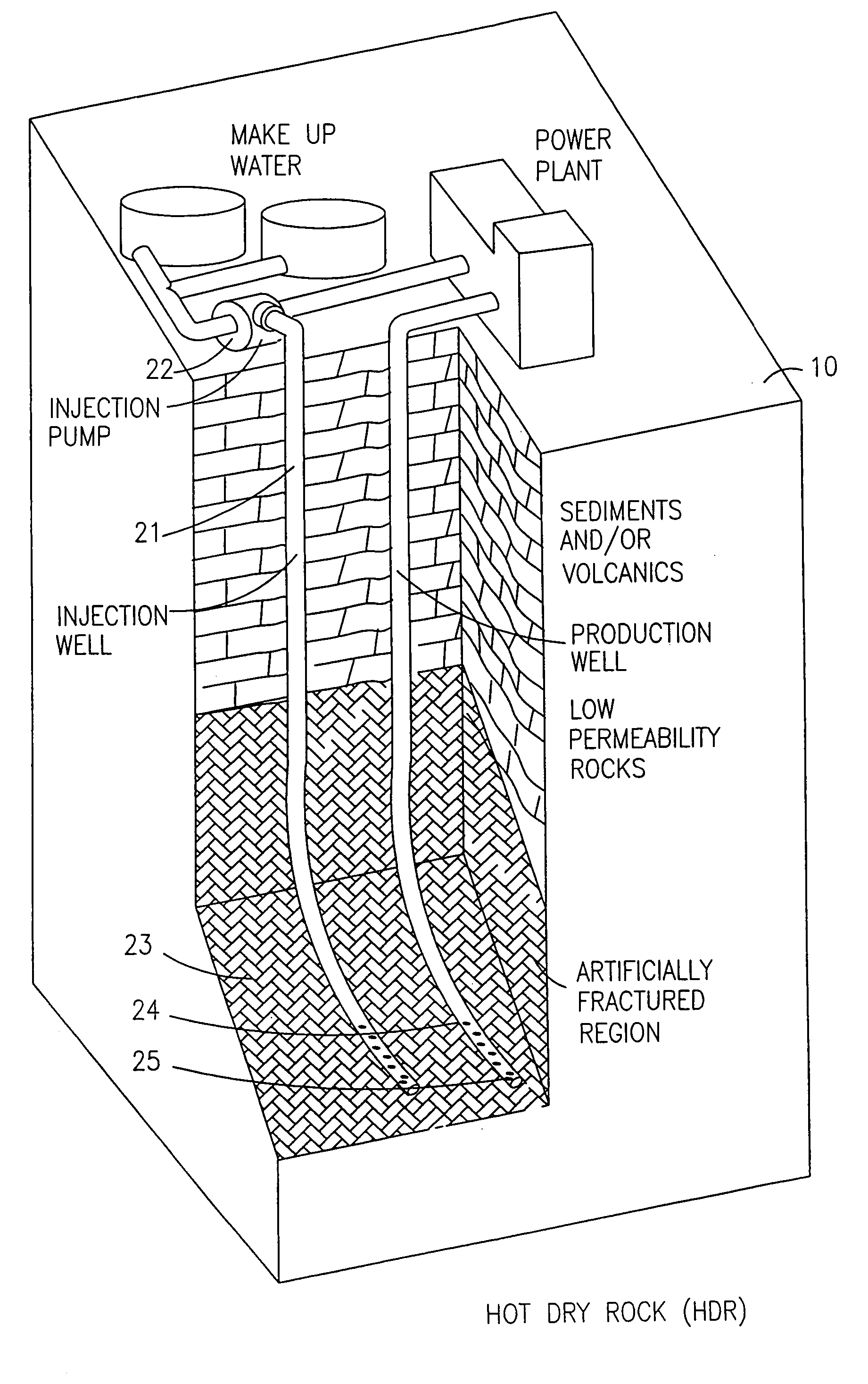
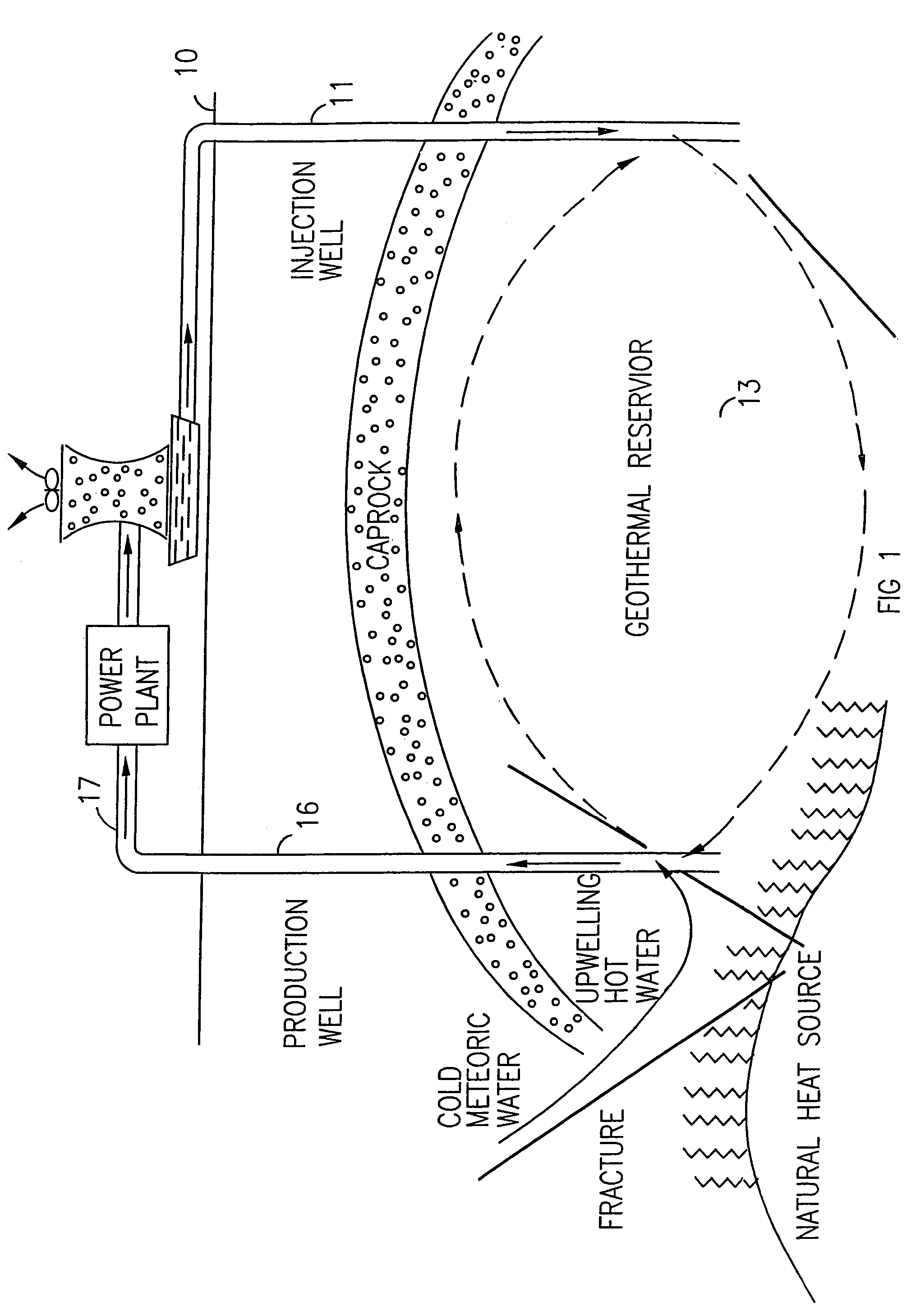
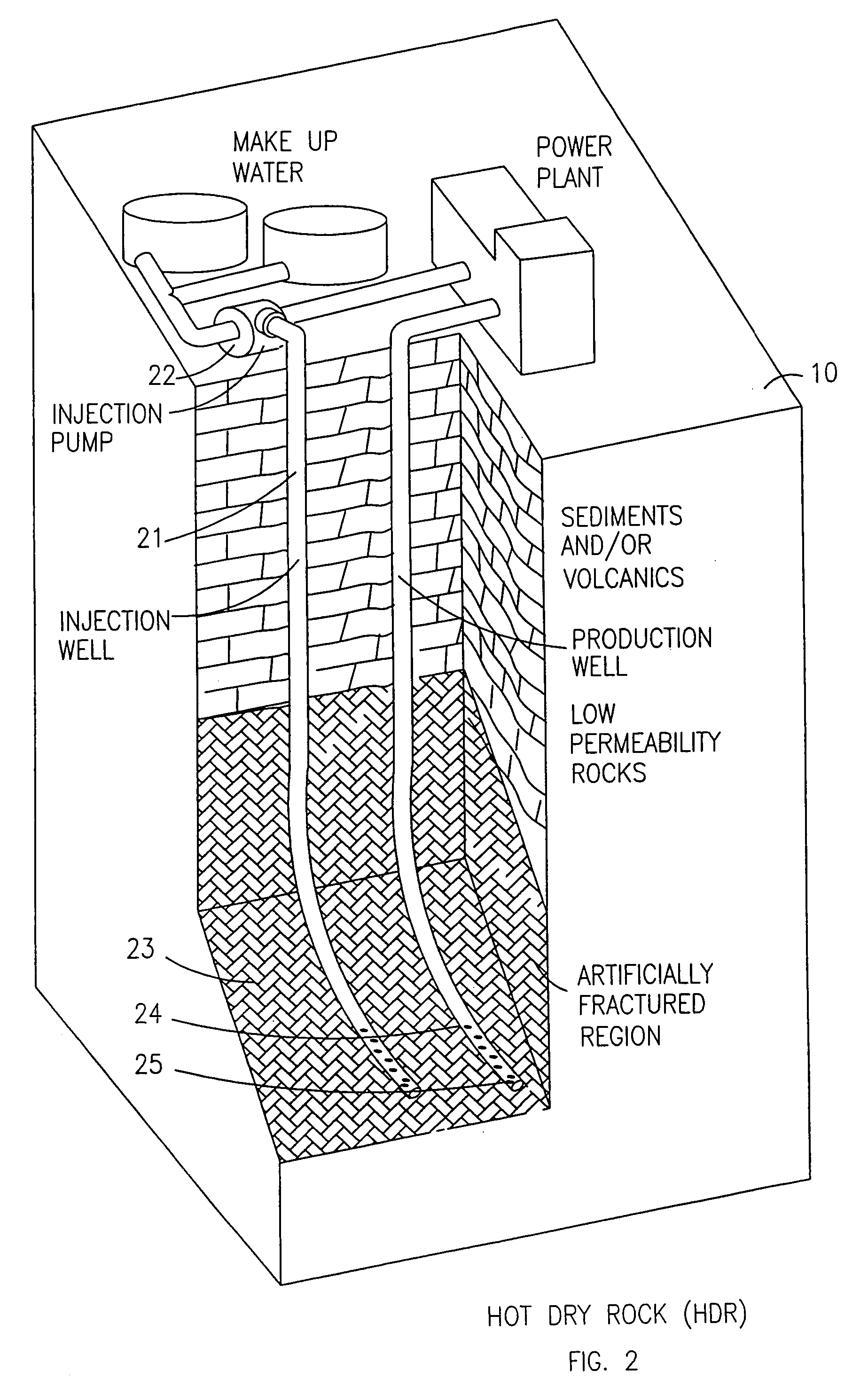
While commercial production of geothermal fluids (e.g. for power production) out of a “classical” steam or water dominated reservoirs is pretty well at hand, such production from Hot Dry Rock (HDR) (or Hot Fractured Rock HFR)) or even from reservoirs with low permeability or insufficient water recharge by Enhanced (or Engineered) Geothermal Systems (EGS) is essentially in the research and development stage, due to many problems in their actual industrial application, including difficulties in sustaining circulation of fluids at a high enough rate at reasonable pressure and losses to the surroundings.
Nevertheless, research and development of such systems are being pursed intensively since a large amount of energy is available in such low permeability, semi-dry or dry geothermal reservoirs (Jacquot, 1998).
In such prior art Hot Dry Rock (HDR) / Hot Fractured Rocks (HFR) set-ups the production of geothermal fluids is limited by the permeability of the layers and by their thickness, and in case of fractures by the width of the fractures.
The injection pumps require energy to be operated and the amount of energy consumed depends on the permeability of the layer between the injection and the production wells, and in some cases becomes a prohibitive fraction of the energy produced.
Other problems are created by the large losses of injected fluid and by the difficulty of producing fractures in the desired direction.
Mainly for these reasons the results of the prior art Hot Dry Rock (HDR) / HFR have been disappointing, to the extent that no power plant exploiting them has been built so far, and their only use today is for limited experimental heat extraction.

Method used


Image

  • Method and apparatus for using geothermal energy for the production of power
  • Method and apparatus for using geothermal energy for the production of power
  • Method and apparatus for using geothermal energy for the production of power

Examples


Embodiment Construction

[0046]In the embodiment of FIG. 8, considered at present the best mode for carrying out the present invention, numeral 30 indicates the ground. Numeral 31 indicates a geological layer that is suitable for the drilling of horizontal wells. Numeral 32 indicates a first (injection) horizontal, geothermal well connected to an injection connection means 33. Numeral 34 indicates a second (production) horizontal, geothermal well connected to production connection means 35. The said two horizontal wells are located in a suitable geological layer 31, first (injection) horizontal, geothermal well 32 being located at a deeper level than shallower, second (production) horizontal geothermal well 34. The suitability of geological layer 31 for such operations and the relative position of said horizontal, geothermal wells are determined by carrying out geophysical surveys and drilling e.g. narrow “slim holes” in said geological layer. Actual core samples or geological cuttings produced from said ge...


PUM


Abstract

An apparatus and method for enhancing the flow of geothermal fluid from at least one injection well to at least one production well, which comprises a first horizontal geothermal well, which is used as the injection well, and into which water is injected; a second horizontal, geothermal well, which is used s the production well and from which geothermal fluid issues, wherein the second, horizontal, production, geothermal well is substantially horizontally and vertically spaced from the first, horizontal, injection, geothermal well and located at a shallower depth than the first, horizontal, injection, geothermal well; and the apparatus form producing a pressure difference between the first horizontal, injection well and the second horizontal, production well and utilizing the water density difference induced by the temperature difference. Preferably, binary geothermal power plants or combined cycle geothermal power plants can be used to produce power from geothermal fluid recovered from the production well.

Description

FIELD OF THE INVENTION[0001]The present invention relates to method and apparatus for the use of geothermal energy for the production of power, more specifically to method and apparatus for enhancing the flow of geothermal fluid from an injection well to a production well (or wells), from which it is conveyed to a power plant or to a heat exchanger in order to use its heat to produce power or for other purposes. This applies for both configurations of such a flow: the “classical” water dominated reservoir, the Enhanced Geothermal System (EGS) as well as the Hot Dry Rock (HDR) or Hot Fractured Rock (HFR) artificially stimulated reservoir.BACKGROUND OF THE INVENTION[0002]Geothermal energy recovery systems, which apply geothermal energy to the production of power, are the object of a considerable amount of attention in the prior art (DiPippo, R. et al., Brown University, U.S.A., DOE, March 1980). While commercial production of geothermal fluids (e.g. for power production) out of a “cla...

Claims


Application Information

Patent Timeline
Patent Type & Authority Patents(United States)
IPC IPC(8): F03G7/00
CPCF02C1/05F03G7/00Y02E20/16F05D2260/20
Inventor BRONICKI, LUCIEN Y.
Owner ORMAT TECH INC
Learn More