
Apparatus and method for accurate, real-time measurement of pipeline gas

a pipeline gas and real-time measurement technology, applied in the direction of instruments, specific gravity measurement, material analysis using wave/particle radiation, etc., can solve the problems of affecting the application in which it is used, requiring bulky or expensive equipment, and not being able to achieve accurate heating value measurement

Inactive Publication Date: 2008-01-08
GAS TECH INST
View PDF6 Cites 2 Cited by
  • Summary
  • Abstract
  • Description
  • Claims
  • Application Information

AI Technical Summary

Benefits of technology

This patent describes a method and apparatus for accurately measuring the heating value of hydrocarbon fuel gases, particularly natural gas. The apparatus includes a reference gas spherical acoustic resonator and a sample gas spherical acoustic resonator, which are filled with the natural gas sample. The method involves propagating an acoustic signal through the reference gas and the natural gas sample, measuring a radial frequency, and calculating the heating value of the natural gas sample based on the specific gravity of the sample. The technical effects of this patent include accurate and continuous measurement of the heating value of natural gas in real-time, as well as in remote locations.

Problems solved by technology

The presence of such other components, in addition to affecting the heating value of the natural gas, may also affect the applications in which it is used, particularly applications which are sensitive to heat input.
However, these methods typically employ bulky or expensive equipment and are less than ideal for in-situ measurements.
However, at least some of these devices are susceptible to numerous sources of error such as the composition of the sample gas and the age and composition of the sensor being utilized.
However, in many instances, tests on a low pressure loop yielded errors from 1 to 4% in the sonic speed measurements.

Method used


Image

  • Apparatus and method for accurate, real-time measurement of pipeline gas
  • Apparatus and method for accurate, real-time measurement of pipeline gas
  • Apparatus and method for accurate, real-time measurement of pipeline gas

Examples


Embodiment Construction

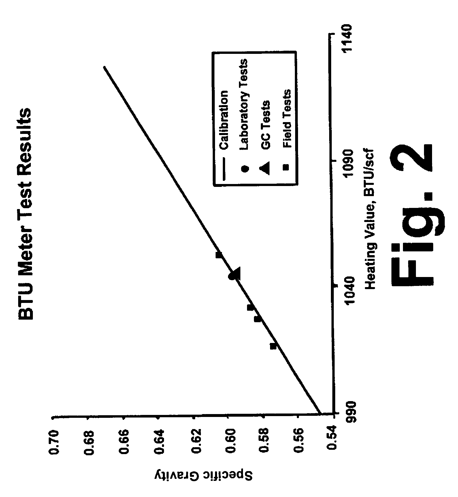
[0020]The invention disclosed and claimed herein is based upon the discovery of a linear relationship between the specific gravity of natural gas and the heating value of natural gas. Accordingly, the method and apparatus of this invention provide a simple means by which the specific gravity of a natural gas sample can be determined from which the heating value, or BTU content, is readily determined.

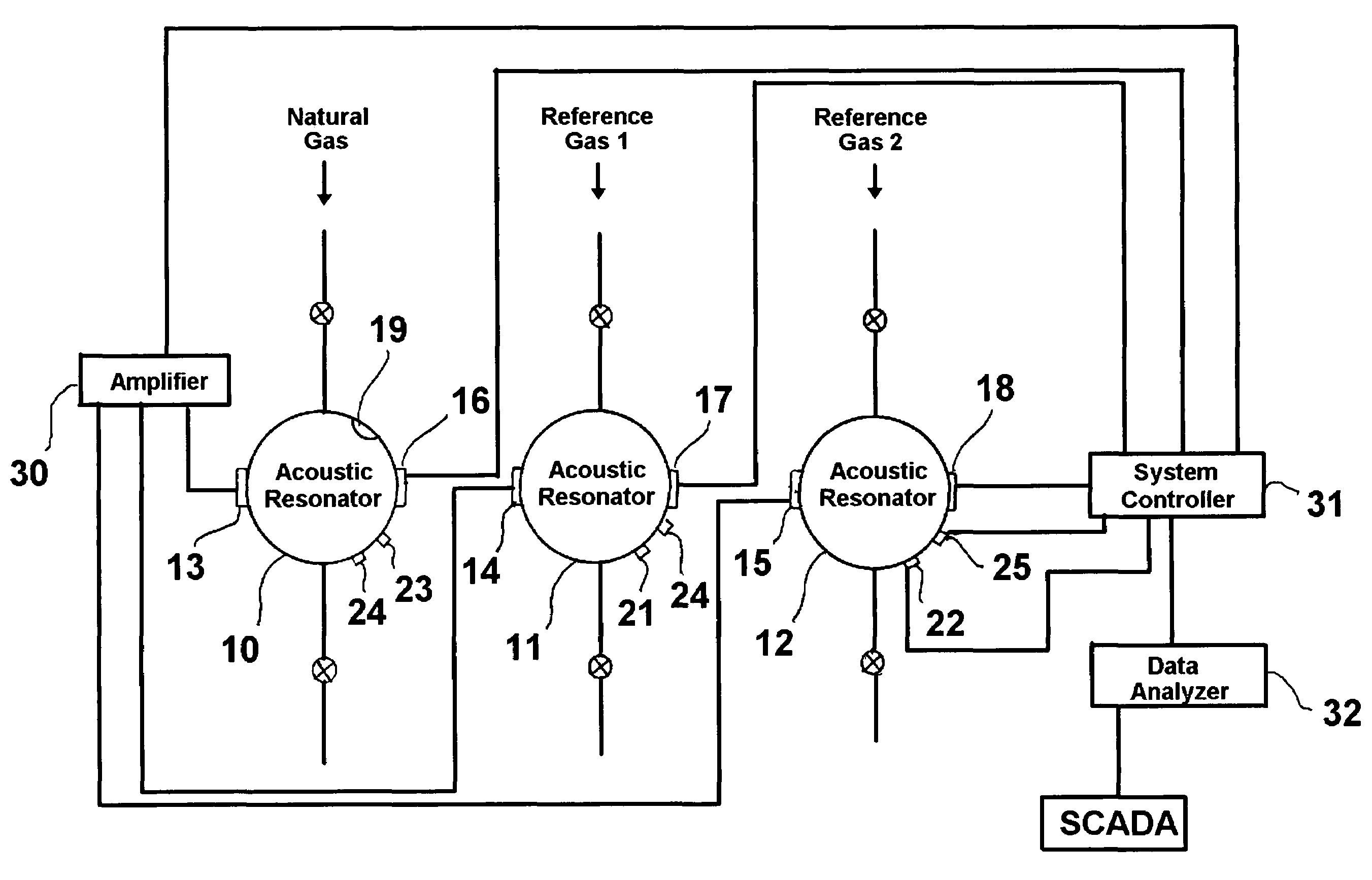
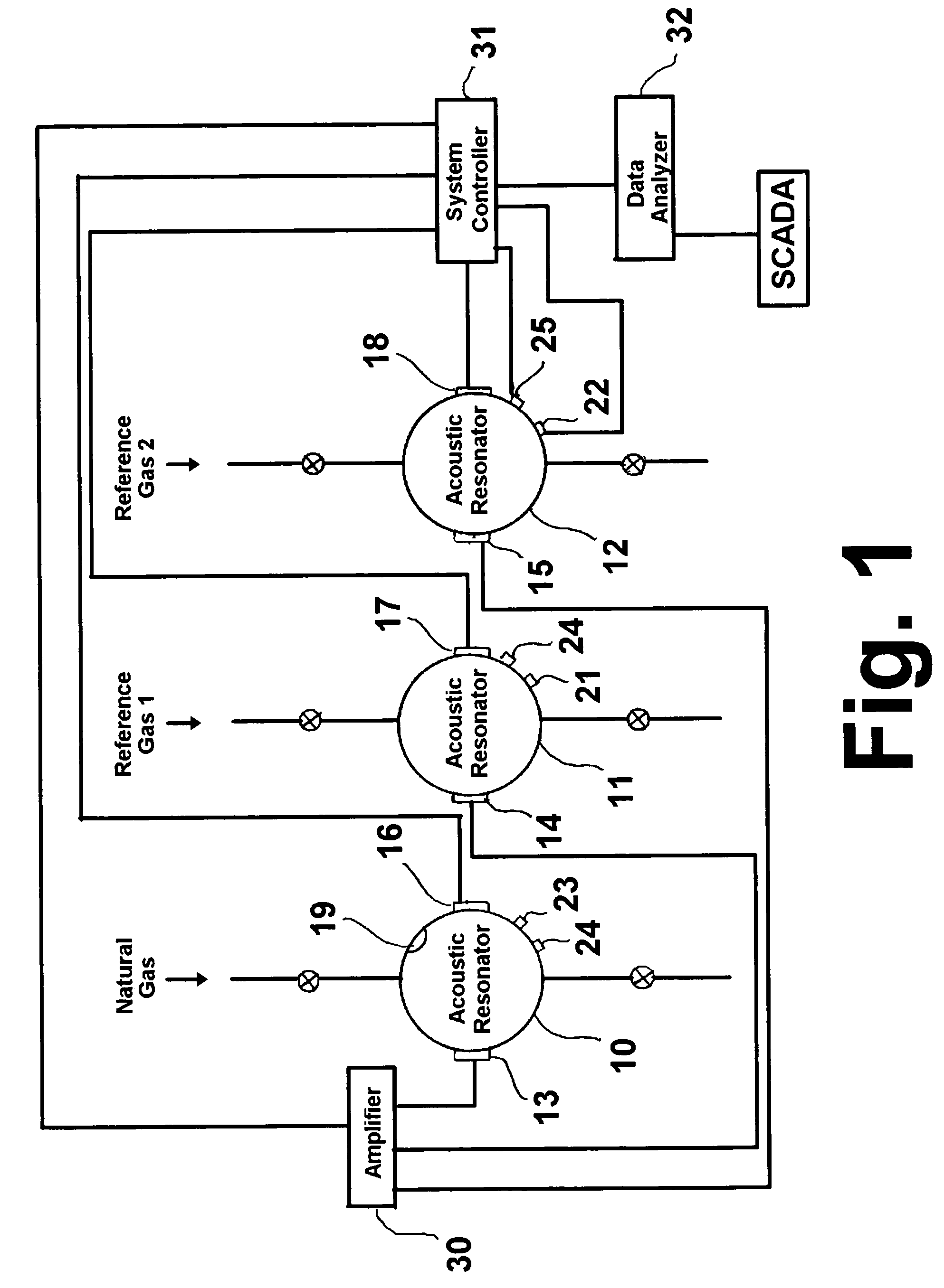
[0021]FIG. 1 is a schematic diagram of a device for real-time BTU measurement of natural gas in accordance with one embodiment of this invention. As shown therein, the device comprises at least two, and preferably three, substantially identical spherical acoustic resonators, 10, 11, 12, one of which is filled with a natural gas sample and the others of which are filled with a reference gas. The reference gas mixture is selected based upon about 6800 gas analyses done from 26 major urban areas located in 19 states and each of the major geographical regions. A different reference gas mixtu...


PUM

PropertyMeasurementUnit
frequencyaaaaaaaaaa
internal diameteraaaaaaaaaa
frequenciesaaaaaaaaaa

Abstract

An apparatus for BTU measurement of natural gas having at least one reference spherical acoustic resonator containing a reference gas, a sample gas spherical acoustic resonator containing a natural gas sample, a first acoustic transmitter adapted to transmit a first acoustic signal into the natural gas sample, a second acoustic transmitter adapted to transmit a second acoustic signal into the reference gas, a first acoustic receiver adapted to receive at least a portion of the first acoustic signal, and a second acoustic receiver adapted to receive at least a portion of the second acoustic signal. Using the third radial resonance frequencies for the sample gas and reference gas, a data processor operably connected with a signal output of the first acoustic receiver determines the specific gravity of the natural gas sample. The discovered linear relationship between specific gravity and heating value of natural gas enables a determination of the heating value from the measured specific gravity.

Description

BACKGROUND OF THE INVENTION[0001]1. Field of the Invention[0002]This invention relates to a method and apparatus for determining the Btu value of fuel gases. More particularly, this invention relates to a method and apparatus for determining the BTU value of pipeline gas in real time.[0003]2. Description of Related Art[0004]Accurate measurement of the heating value, i.e. BTU content, of hydrocarbon fuel gases is an essential component of their efficient and cost-effective use in a wide variety of applications. The heating value of natural gas, which typically contains in the range of about 80% to nearly 100% by weight methane, generally varies between about 900 and 1300 BTU / ft3 depending upon the composition of the natural gas. In addition to methane, natural gas may contain various amounts of other hydrocarbons, such as ethane, propane, butane and non-hydrocarbons, such as CO2 and N2. The presence of such other components, in addition to affecting the heating value of the natural g...

Claims


Application Information

Patent Timeline
Patent Type & Authority Patents(United States)
IPC IPC(8): G01N9/36G01N23/00
CPCG01N29/036G01N29/30G01N2291/0215
Inventor SIVARAMAN, ALWARAPPA
Owner GAS TECH INST
Learn More