
Adjustable depth fishing lure

a depth fishing and adjustable technology, applied in the field of fishing lures, can solve the problems of lures that cannot be easily used, spring will be weakened, and the lure cannot be easily used

Inactive Publication Date: 2008-01-08
PETNER ROBERT E +1
View PDF5 Cites 30 Cited by
  • Summary
  • Abstract
  • Description
  • Claims
  • Application Information

AI Technical Summary

Benefits of technology

"The present invention is an adjustable fishing lure that has several technical effects. It can be easily adjusted to control the depth at which it moves through the water, and it can be adjusted many times without breaking or becoming worn out. The lure allows for smooth passage of fishing line through it, and it can be adjusted to a desired depth without disturbing the connection with the fishing line and hook. The lure is also easy to adjust on site by a single user without the need for tools. It moves and oscillates as it is drawn through the water, which attracts fish. The lure has a simple structure and is inexpensive to manufacture."

Problems solved by technology

The configuration of the lure will not withstand the forces caused by prolonged movement through the water, subjecting it to premature breakage.
Such a lure also cannot easily be used without disturbing the fishing line / hook connections to the lures.
Most critically, the lure represents a fatally flawed design, in that after several diving lip adjustments, the tension in the spring will be weakened and its ability to securely position the lip, especially as the lure is pulled through water and the lip is subject to high water pressure, will be severely compromised.
The lure will quickly become inoperable and ineffective as an adjustable unit.

Method used


Image

  • Adjustable depth fishing lure
  • Adjustable depth fishing lure
  • Adjustable depth fishing lure

Examples


Embodiment Construction

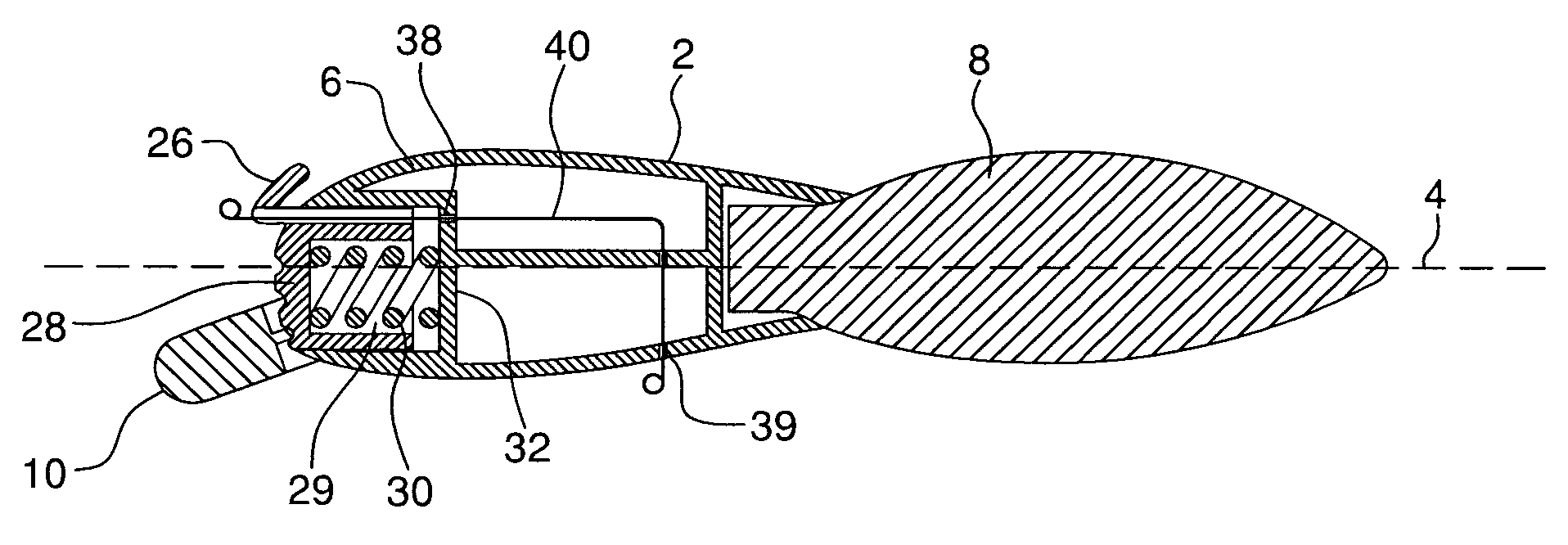
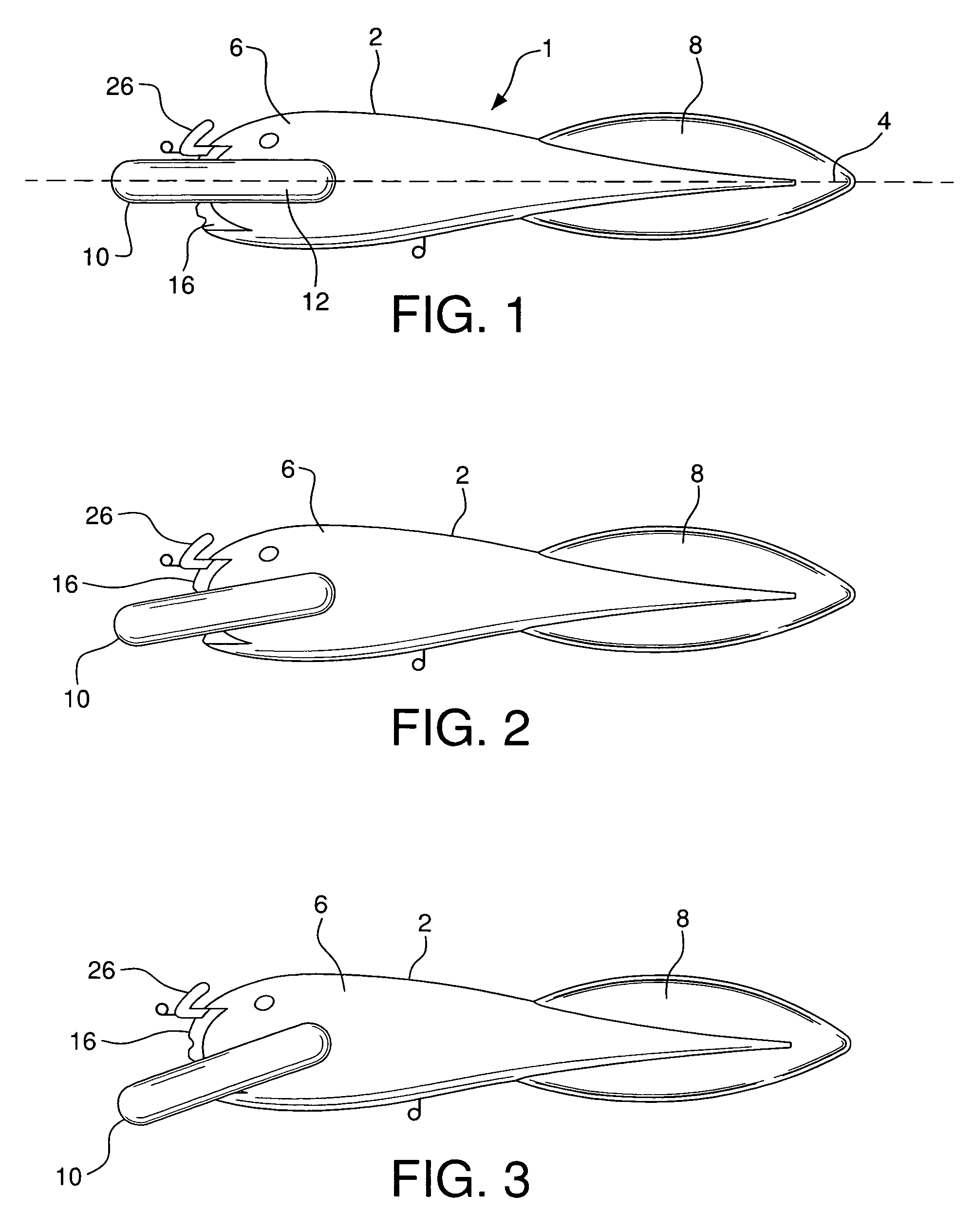
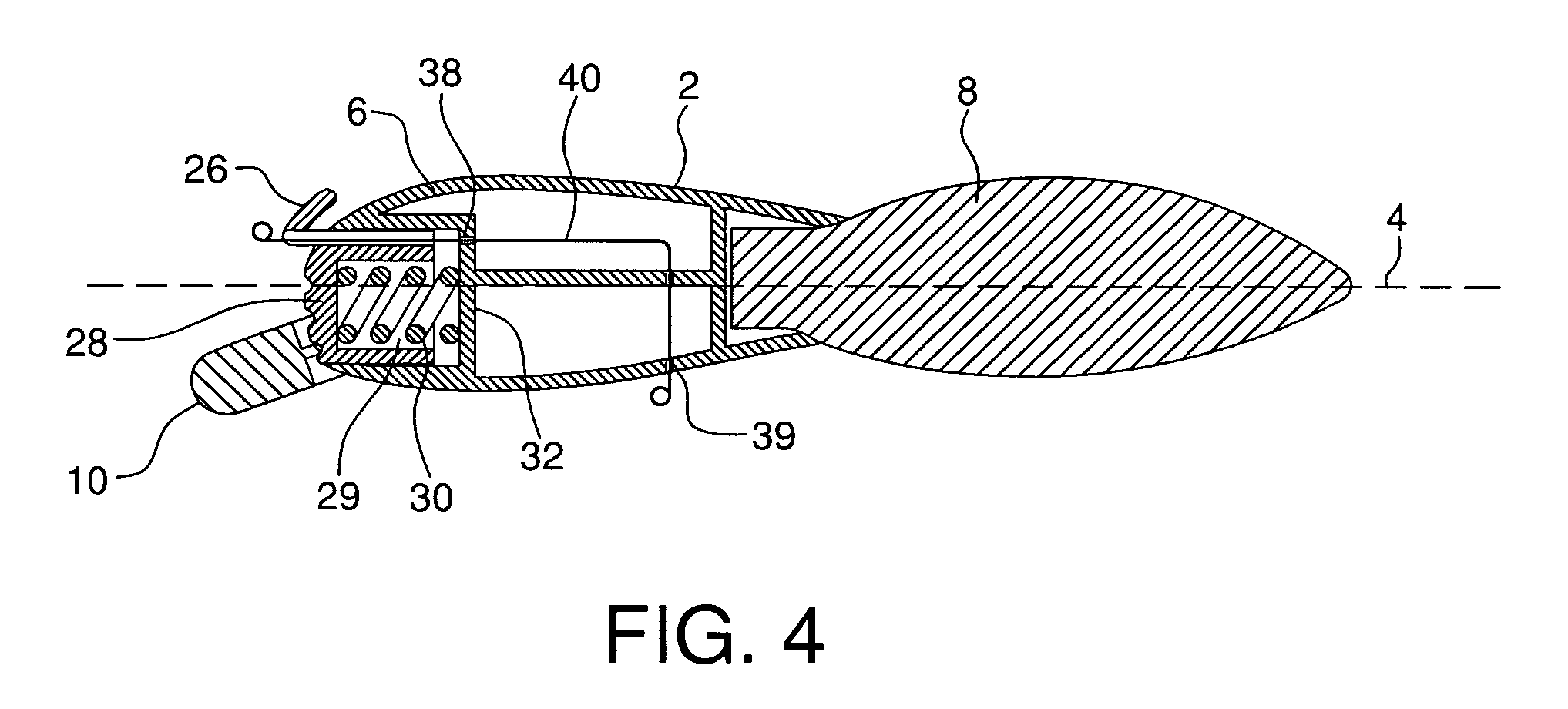
[0021]Fishing lure 1 of the present invention comprises elongated lure body 2 having longitudinal axis 4. Body 2 comprises forward section 6 and tail section 8. Diving lip 10 has arm members 12 and 14 which are pivotably mounted externally of forward section 6 of lure body 2 by inwardly extending pin members 13 and 15 positioned within indented side openings of the body. One such opening 17 is seen in FIG. 5. Located within and extending outwardly from forward section 6 is control element 16. Slots 18, 20, and 22, indented into the external surface of front wall 28 of control element 16, are configured to receive internal cut-out 24 of diving lip 10. Tab element 26 extends outward from control element 16 and is designed to be pushed, to move the control element rearward of lure body 2, along its longitudinal axis 4.

[0022]Control element 16 also has front wall 28 and internal space 29 which is configured to house biased spring 30. Spring 30 is located within space 29, between control...


PUM


Abstract

An adjustable depth fishing lure has a lure body with forward and tail sections. A diving lip is pivotably attached to the forward section of the body by dual arm members. The diving lip is configured to be adjustably positioned at a plurality of angles in relation to the lure body by a control element located within the forward section. The control element has a plurality of slots into which the diving lip can be set. A push tab extends from the element. A spring is positioned between a front wall of the forward section and the control element. The spring applies a compressive force against the control element, which biases the element against the diving lip to maintain it in one of the plurality of slots. When the control element's tab is pushed, the element travels inward into the forward section, which releases the pressure on the diving lip, allowing it to be repositioned into another of the slots. Through-openings within the lure body allow for free and independent movement of fishing line through the lure. The forward and tail sections can be separate, independent elements which are pivotably connected to oscillate as the lure is drawn through the water, to further attract fish.

Description

BACKGROUND OF THE INVENTION[0001]The use of fishing lures, especially lures which have the appearance of and are shaped like minnows or similar small fish, are often used as artificial bait to attach and catch specific fish. Since different types of fish are located at different water depths, adjustable depth lures are employed to run at different water depths. Many of these lures comprise weights attached to position the lures at desired depths. Other lures are configured to be adjustable and, when appropriately set, will dive and run through shallow, medium or deep waters, when drawn through the water at given velocities. In such configurations, the fishing line is routinely attached to the front end of the lure and an adjustable diving element, plate, or lip, extends forward of the front end. The forces applied on the lip acting against the water as the lure is drawn through the water, causes the lure to dive or surface, depending on the position of the lip. The depth to which th...

Claims


Application Information

Patent Timeline
Patent Type & Authority Patents(United States)
IPC IPC(8): A01K85/00A01K85/16
CPCA01K85/16A01K85/18
Inventor PETNER, ROBERT E.ROMANO, DANIEL
Owner PETNER ROBERT E
Learn More