
Electrical measuring instrument having detachable current clamp

a current clamp and electric measuring technology, applied in the direction of instruments, dc-ac conversion measurement, base element modification, etc., can solve the problems of raising reliability problems, difficult to individually disconnect the wire of interest, and inconvenient disconnection of the wire to connect the current meter

Active Publication Date: 2007-12-25
JOHN FLUKE MFG CO INC
View PDF3 Cites 32 Cited by
  • Summary
  • Abstract
  • Description
  • Claims
  • Application Information

AI Technical Summary

Problems solved by technology

In many cases, however, disconnecting the wire to connect the current meter can be inconvenient.
For example, the wire can be tightly grouped in a bundle with several other wires making it difficult to individually disconnect the wire of interest.
Another example of the inconvenience is where a terminal to which the wire is connected is not conveniently located or is inaccessible, requiring the wire to be cut for the current meter to be connected in series.
It is time consuming to reconnect the two ends of the cut wire after a measurement is taken, and can be dangerous in situations where relatively high current is carried by the wire.
Additionally, the integrity of the wire is compromised by cutting and reconnecting, thus, potentially raising reliability problems.
Additionally, since the clamp probe is an attachment to the multimeter, it is typically stored separately from the meter, which can be inconvenient when carrying the equipment around and can also be easily misplaced when not used.
However, problems with reading the measurement can arise where the wire is difficult to reach or is positioned such that the display of the meter is obscured when the meter is in position for measurement.
In one case, the technician must put himself in a physically uncomfortable and potentially dangerous position when attempting to view the measured value on the display of an awkwardly positioned meter.
In the other case, removing the meter from a wire that was difficult to clamp in the first place is inconvenient and can be time consuming if the clamp meter must be re-clamped to take additional measurements from the same wire.
However, in addition to the disadvantages previously discussed, these meters also lack the convenience of one-handed measurements for applications where it is possible to do so.
This is a costly solution since two different meters need to be purchased, although only one meter is typically used at a time for taking a measurement.

Method used


Image

  • Electrical measuring instrument having detachable current clamp
  • Electrical measuring instrument having detachable current clamp
  • Electrical measuring instrument having detachable current clamp

Examples


Embodiment Construction

[0017]Certain details are set forth below to provide a sufficient understanding of the invention. However, it will be clear to one skilled in the art that the invention may be practiced without these particular details. Moreover, the particular embodiments of the present invention described herein are provided by way of example and should not be used to limit the scope of the invention to these particular embodiments. In other instances, well-known circuits, control signals, timing protocols, and software operations have not been shown in detail in order to avoid unnecessarily obscuring the invention.

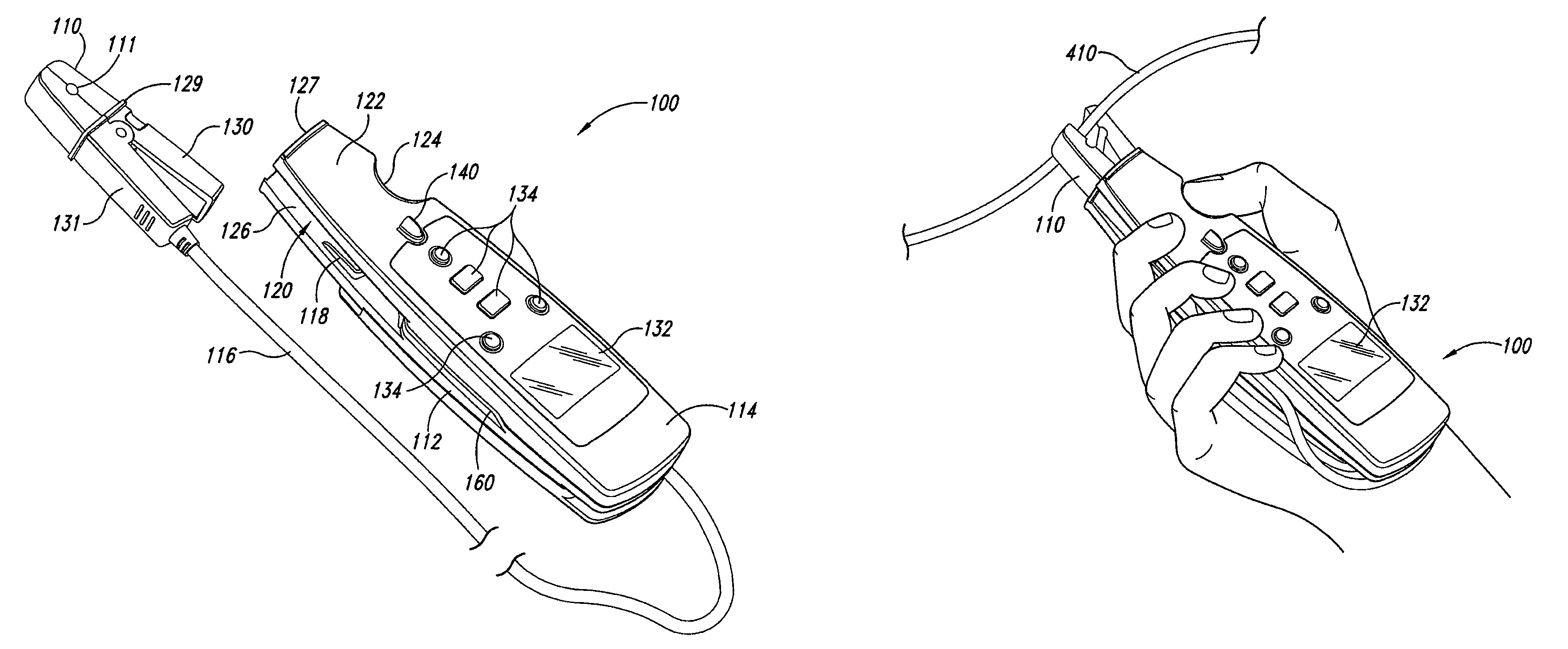
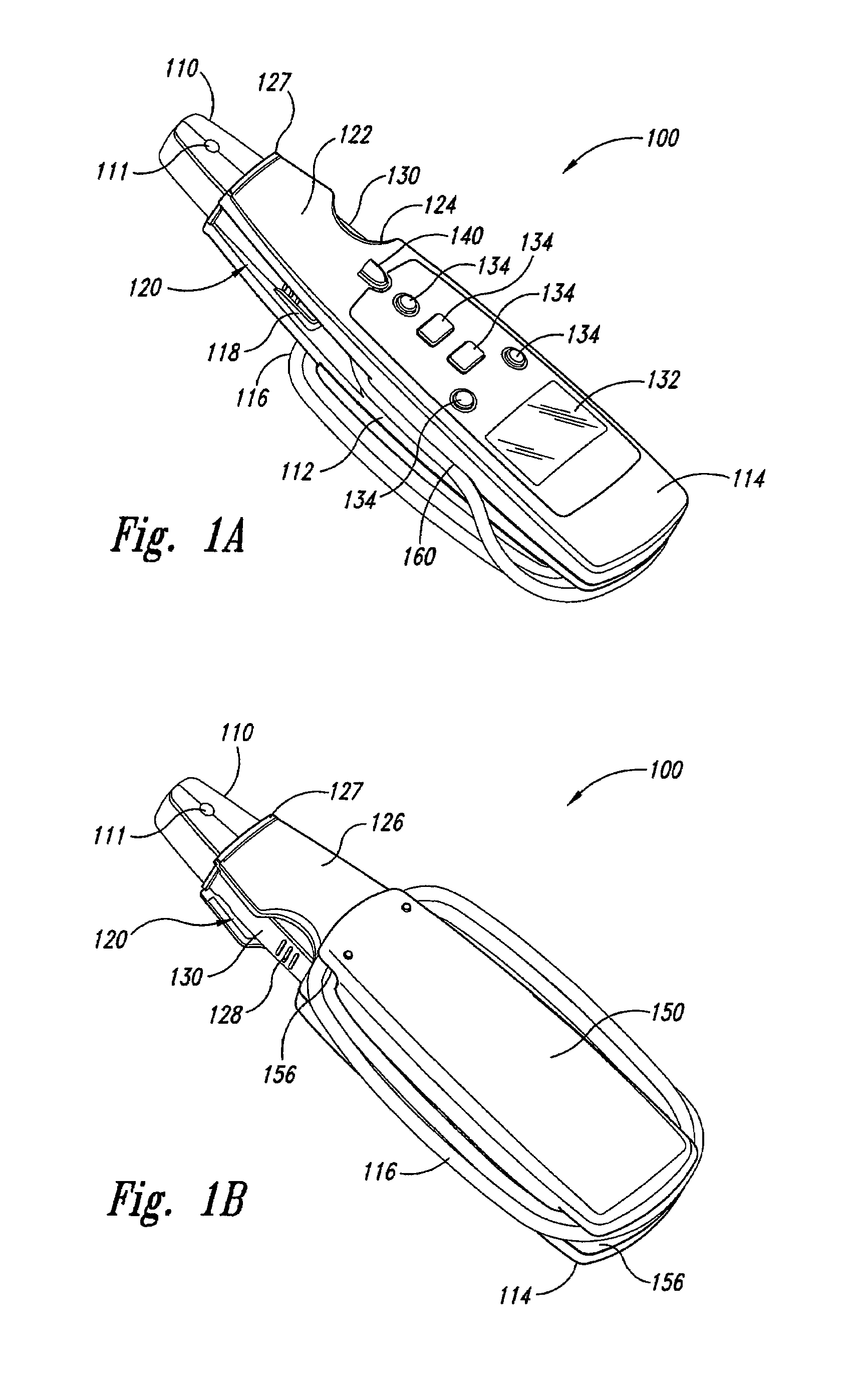
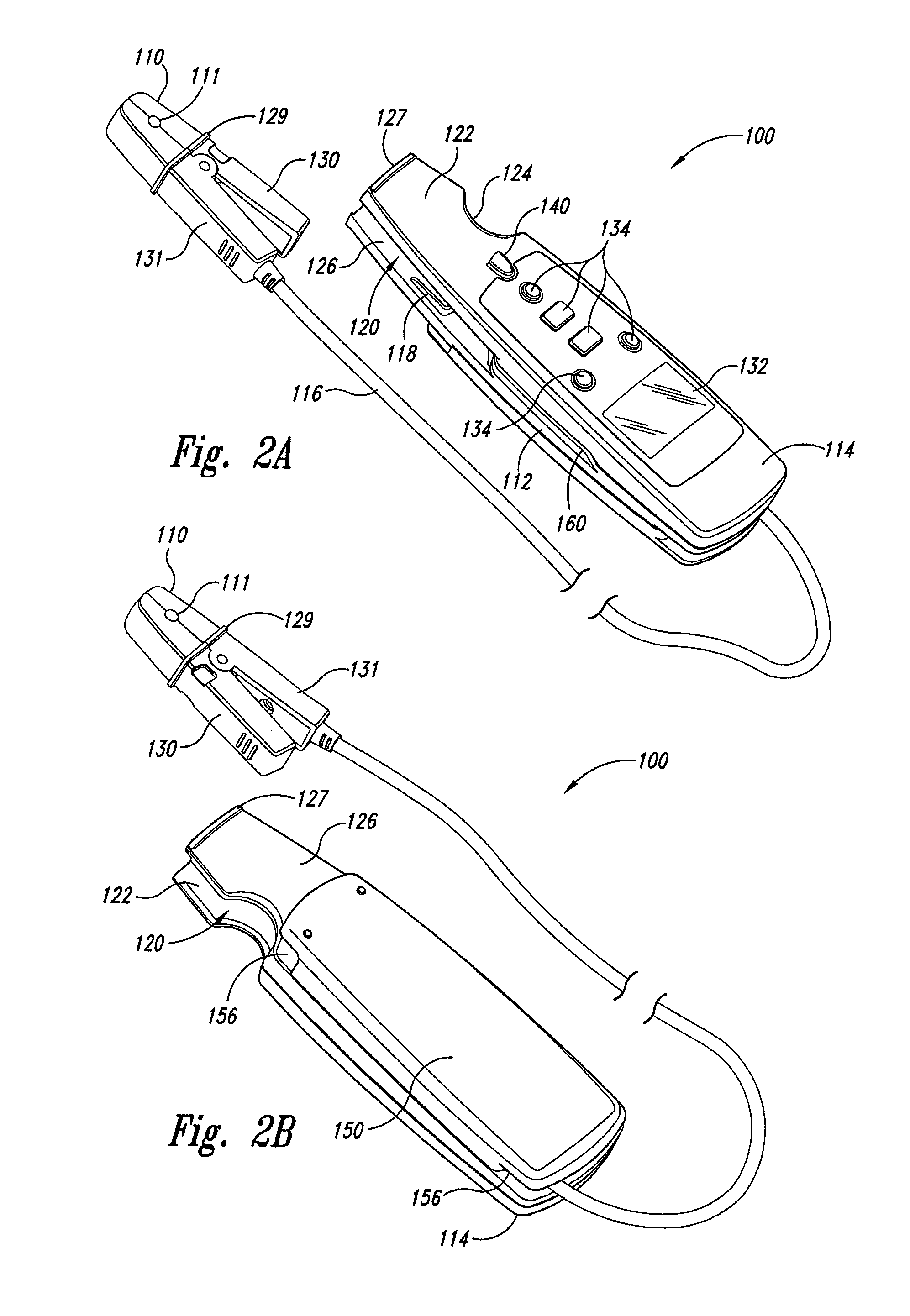
[0018]FIGS. 1A and 1B illustrate a clamp meter 100 according to an embodiment of the present invention. As will be described in more detail below, the clamp meter 100 includes a current clamp probe 110 that is detachable from a housing 112 in which circuitry for the clamp meter 100 are encased. The clamp probe 110 includes a current sensor for detecting current in a wire positioned in a...


PUM


Abstract

A current clamp meter having a current meter body and a detachable current clamp. The current meter body and the current clamp are configured so that the current clamp is detachable from the current meter body and the meter is operable with the current clamp either attached to the current meter body or detached from the current meter body.

Description

CROSS-REFERENCE TO RELATED APPLICATION[0001]This application is a divisional of pending U.S. patent application Ser. No. 11 / 414,655, filed Apr. 27, 2006.TECHNICAL FIELD[0002]This invention generally relates to electronic test tools, and more specifically, to a current clamp meter having a detachable current clamp that can be used to measure current with the current clamp attached or detached from the meter.BACKGROUND OF THE INVENTION[0003]Electrical current can be measured by connecting a current meter in series with the wire. In many cases, however, disconnecting the wire to connect the current meter can be inconvenient. For example, the wire can be tightly grouped in a bundle with several other wires making it difficult to individually disconnect the wire of interest. Another example of the inconvenience is where a terminal to which the wire is connected is not conveniently located or is inaccessible, requiring the wire to be cut for the current meter to be connected in series. It...

Claims


Application Information

Patent Timeline
Patent Type & Authority Patents(United States)
IPC IPC(8): G01R15/18
CPCG01R1/22G01R1/06788G01R1/04G01R15/18
Inventor LUO, SHOUNANYONG, WANG
Owner JOHN FLUKE MFG CO INC
Learn More