
Air passage switching device

a switching device and air passage technology, applied in the direction of vehicle heating/cooling devices, railway components, domestic heating, etc., can solve the problem of difficult to reduce the size of the air passage switching device, and achieve the effect of simple electric connection structure of the motor

Inactive Publication Date: 2007-12-25
DENSO CORP
View PDF20 Cites 3 Cited by
  • Summary
  • Abstract
  • Description
  • Claims
  • Application Information

AI Technical Summary

Benefits of technology

This design effectively reduces the overall size of the device by integrating the actuator and deceleration mechanism, minimizing friction through internal placement and providing a simple electrical connection structure, enabling precise control of air passage opening and closing.

Problems solved by technology

However, a drive actuator for rotating and moving the winding shaft and a rotation mechanism are mounted outside the winding shaft, and it is difficult to reduce the size of the air passage switching device.

Method used


Image

  • Air passage switching device
  • Air passage switching device
  • Air passage switching device

Examples


first embodiment

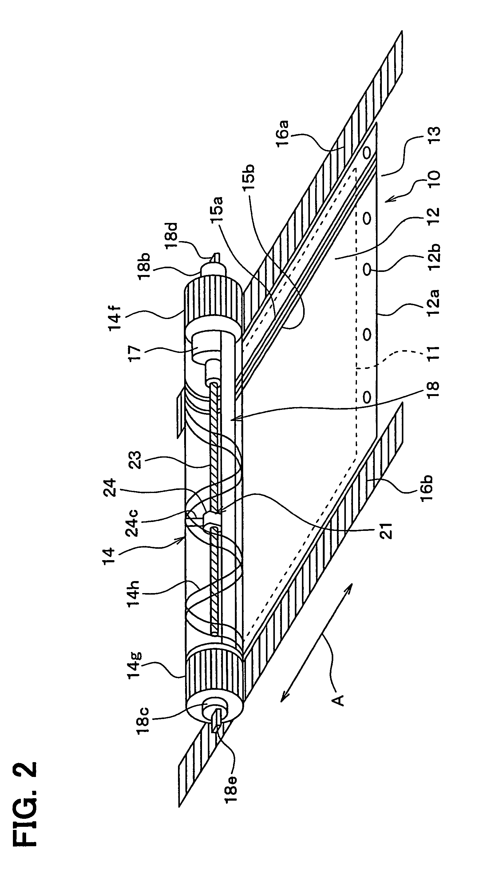
[0022]In this embodiment, an air passage switching device for opening and closing an opening portion of an air passage is typically used for a vehicle air conditioner, for example.

[0023]An air conditioning casing 10 of the air conditioner is made of resin and forms an air passage through which air flows into a compartment, e.g., a passenger compartment of the vehicle. A rectangular opening portion 11 through which air flows is formed in the air passage of the air conditioning casing 10.

[0024]A film member 12 is arranged on an upstream air side (e.g., upper side in FIG. 1) of a periphery of the opening portion 11. In this embodiment, a seal surface 13 is provided on the upstream portion of the opening portion 11 in the air conditioning casing 10, and the film member 12 is arranged to contact the seal surface 13.

[0025]As an example, the opening portion 11 is an opening portion of a cool air passage or / and a warm air passage within the air conditioning casing 10. Cool air cooled by a c...

second embodiment

[0065]In the above-described first embodiment, electrical power is supplied to the motor 17 accommodated inside the winding shaft 14 through the electrical conductive members 15a, 15b of the film member 12, the conductor members 26a, 26b of the cylindrical body portion 14a, the collector rings 25a, 25b and the motor terminal members 17b, 17c. In the second embodiment, as shown in FIG. 6, positive and negative motor lead wires (terminal connectors) 17d, 17e electrically connected to the motor 17 are extended to an exterior of the side wall 19a of the air conditioning casing 10 through an interior of the shaft portion 18b and an interior of the movable guide portion 18d of the motor fixing portion 18. In this embodiment, it is unnecessary to provide the electrical conductive members 15a, 15b of the film member 12, the conductor member 26a, 26b of the winding shaft 14 and the collector rings 25a, 25b described in the first embodiment. Therefore, electrical connection structure to the m...


PUM


Abstract

An air passage switching device includes a film member for opening and closing an opening portion of an air passage, and the film member has a first end portion fixed to a peripheral portion of the opening portion and a second end portion fixed to a winding shaft. The winding shaft is capable of moving in a first direction separated from the first end portion of the film member and in a second direction approaching the first end portion of the first member while rotating. In the air passage switching device, an actuator for operating the winding shaft is disposed in an interior of the winding shaft and is fixed by a fixing member, the winding shaft is disposed rotatably relative to the fixing member, and the fixing member is moved in the first direction or the second direction together with the winding shaft by a guide unit.

Description

CROSS REFERENCE TO RELATED APPLICATION[0001]This application is based on Japanese Patent Application No. 2004-189408 filed on Jun. 28, 2004, the contents of which are incorporated herein by reference in its entirety.FIELD OF THE INVENTION[0002]The present invention relates to an air passage switching device for opening and closing an air passage using a film member of a film door. The air passage switching device may be suitably used for a vehicle air conditioner.BACKGROUND OF THE INVENTION[0003]In an air passage switching device described in JP-A-5-238244, two ends of a film member having openings are respectively connected to shafts and are wound on or rewound from the shafts, so that the film member is moved in an air conditioning case. Therefore, the openings of the film member are moved relative to an air passage of the air conditioning case, and an opening portion of the air passage of the air conditioning case is opened and closed.[0004]In this case, because the film member i...

Claims


Application Information

Patent Timeline
Patent Type & Authority Patents(United States)
IPC IPC(8): F24F7/007B60H1/00B60H1/34F16K7/18F16K31/04
CPCB60H1/00692F16K31/04F16K7/18Y10S251/901
Inventor TOKUNAGA, TAKAHIROTAKEUCHI, TOKUHISAITO, MASAHIROITO, KOJI
Owner DENSO CORP
Learn More