
Thermally assisted recording of magnetic media using a resonant cavity and energy

a magnetic media and energy technology, applied in the field of magnetic heads, can solve the problems of difficult to bring photons to such devices, apply near field optical devices, and inapplicability of conventional diffraction limited optics for such a small area, and achieve the effect of facilitating data writing and lowering localized coercivity

Active Publication Date: 2007-12-18
WESTERN DIGITAL TECH INC
View PDF11 Cites 14 Cited by
  • Summary
  • Abstract
  • Description
  • Claims
  • Application Information

AI Technical Summary

Benefits of technology

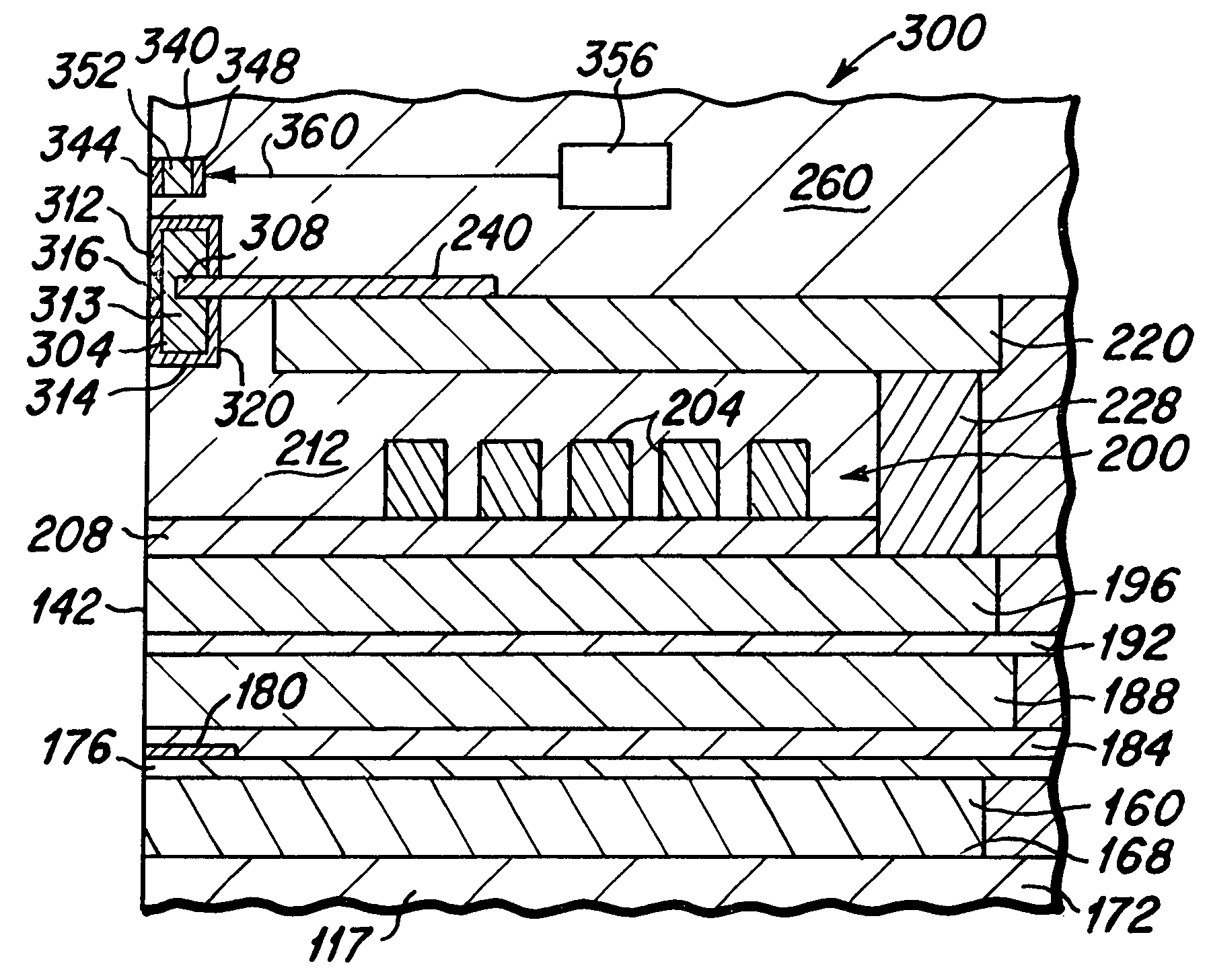
The present invention relates to a magnetic head with improved media heating and an optical resonant cavity media heating device. The heating device helps to lower the coercivity of the media, making it easier to write data to the media. The magnetic head also includes an optical cavity resonator that produces a high intensity near-field optical beam for perpendicular recording at 1 Tbits / in2 and beyond. The magnetic head is designed to facilitate high efficiency coupling of light from a source into the media. The hard disk drive that includes this magnetic head has improved data storage density and can write to disks with higher coercivity. The media heating element can be disposed close to the write pole of the magnetic head, providing a heated spot that is scalable as bit density increases. The invention is advantageous for achieving higher data storage capacity and writing to high-bit density disks.

Problems solved by technology

Conventional diffraction limited optics is not applicable for such a small area.
Much of the difficulty in applying near field optical devices for TAR lies in their incompatibility with the space-limited mechanical structure of the write poles within a magnetic head, the difficulty in bringing photons to such devices, and meeting the requirements for producing a near field high intensity optical beam that is within about 10 nm from the bit area that is being written.

Method used


Image

  • Thermally assisted recording of magnetic media using a resonant cavity and energy
  • Thermally assisted recording of magnetic media using a resonant cavity and energy
  • Thermally assisted recording of magnetic media using a resonant cavity and energy

Examples


Embodiment Construction

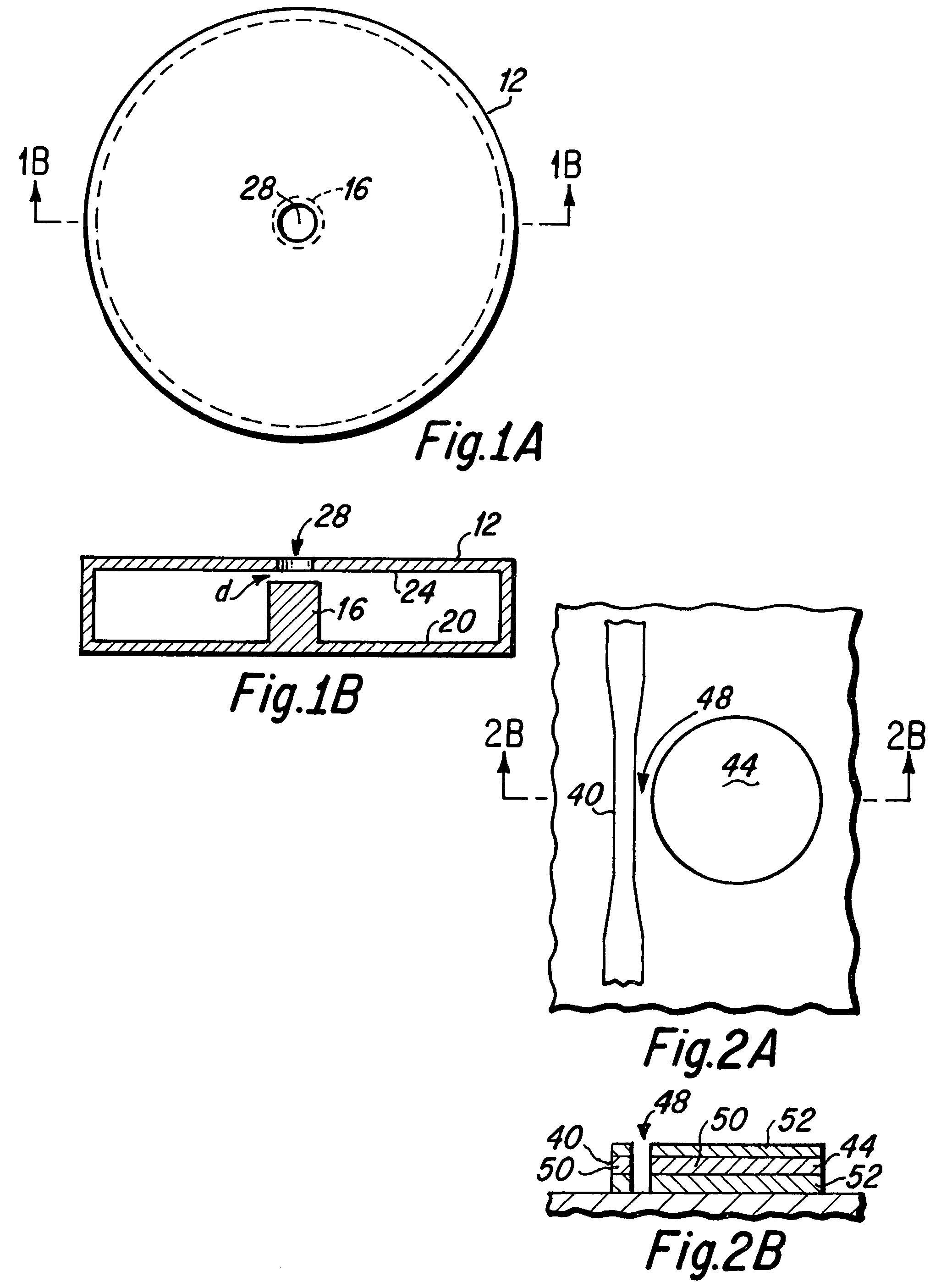
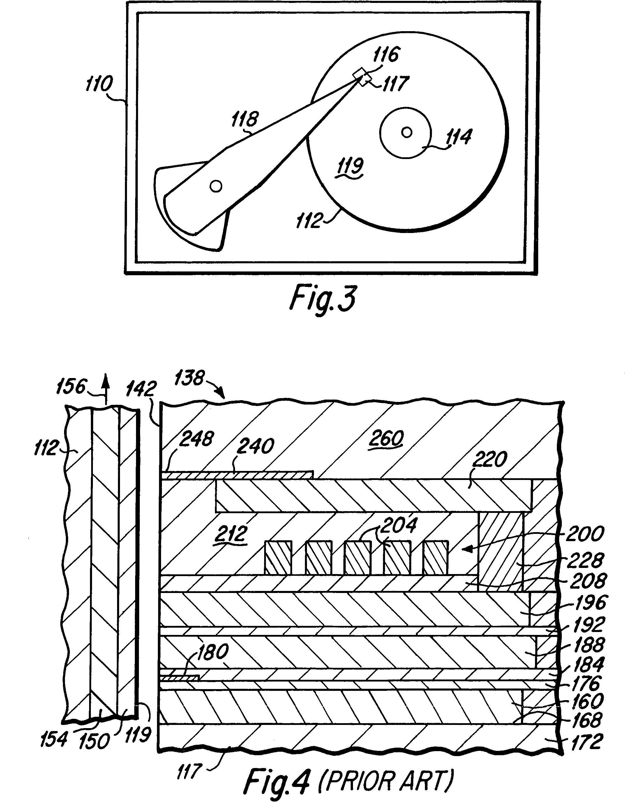
[0035]The magnetic head of the present invention is utilized to read and write data to magnetic media, such as a hard disk in a hard disk drive. A simplified top plan view of a hard disk drive 110 is presented in FIG. 3, wherein at least one magnetic media hard disk 112 is rotatably mounted upon a spindle 114. A magnetic head 116 of the present invention is formed upon a slider 117 that is mounted upon an actuator arm 118 to fly above the surface 119 of each rotating hard disk 112, as is well known to those skilled in the art. A typical hard disk drive 110 may include a plurality of disks 112 that are rotatably mounted upon the spindle 114, and a plurality of actuator arms 118, each having at least one slider 117 with a magnetic head 116 that is mounted upon the distal end of the actuator arms 118. As is well known to those skilled in the art, when the hard disk drive 110 is operated, the hard disk 112 rotates upon the spindle 114 and the slider acts as an air bearing in flying abov...


PUM

PropertyMeasurementUnit
wavelengthaaaaaaaaaa
diameteraaaaaaaaaa
diameteraaaaaaaaaa

Abstract

A magnetic head including a media heating device including an optical cavity resonator that produces a high intensity near-field optical beam adjacent to the write pole. Optical energy is coupled into the resonant cavity through a waveguide that is placed proximate the cavity, and optical energy is coupled out of the cavity through an aperture that is placed proximate an antinode or post within the cavity. The write pole tip may serve as the post in certain embodiments. The media heating device is preferably fabricated between the first and second magnetic pole layers of a perpendicular magnetic head and close to the ABS surface of the head. An alternative embodiment may include a near field aperture disposed between the resonant cavity and the ABS.

Description

BACKGROUND OF THE INVENTION[0001]1. Field of the Invention[0002]The present invention relates generally to magnetic heads that are utilized with thin film hard disk data storage devices, and more particularly to the design and fabrication of a magnetic head having an optical energy resonant cavity storage media heating device formed therein.[0003]2. Description of the Prior Art[0004]Hard disk drives generally include one or more rotatable data storage disks having a magnetic data storage layer formed thereon. Data in the form of small magnetized areas, termed magnetic data bits, are written onto the magnetic layers of the disks by a magnetic head that includes magnetic poles through which magnetic flux is caused to flow. Magnetic flux flowing from a pole tip portion of the magnetic poles in close proximity to the magnetic layer on the disk, causes the formation of the magnetic bits within the magnetic layer.[0005]The continual quest for higher data recording densities of the magneti...

Claims


Application Information

Patent Timeline
Patent Type & Authority Patents(United States)
IPC IPC(8): G11B5/127
CPCG11B5/02G11B5/1278G11B5/314G11B2005/0021G11B2005/0005
Inventor HSU, YIMINPOON, CHIE CHINGSTRAND, TIMOTHY CARL
Owner WESTERN DIGITAL TECH INC
Learn More