
Magnetic head having media heating device that is electrically connected to magnetic pole piece

a heating device and magnetic head technology, applied in the field of magnetic heads, can solve the problems of adding unnecessary complexity and expense to the head fabrication process, and achieve the effect of facilitating data writing and lowering the localized coercivity of the media

Active Publication Date: 2005-09-06
WESTERN DIGITAL TECH INC
View PDF14 Cites 12 Cited by
  • Summary
  • Abstract
  • Description
  • Claims
  • Application Information

AI Technical Summary

Benefits of technology

This approach allows for easier and less expensive fabrication of magnetic heads with integrated media heating devices, enabling higher data areal storage densities and coercivity in hard disk drives by locally reducing coercivity through heat application, facilitating reliable data writing.

Problems solved by technology

Each additional fabrication step adds unwanted complexity and expense to the head fabrication process.

Method used


Image

  • Magnetic head having media heating device that is electrically connected to magnetic pole piece
  • Magnetic head having media heating device that is electrically connected to magnetic pole piece
  • Magnetic head having media heating device that is electrically connected to magnetic pole piece

Examples


embodiment 200

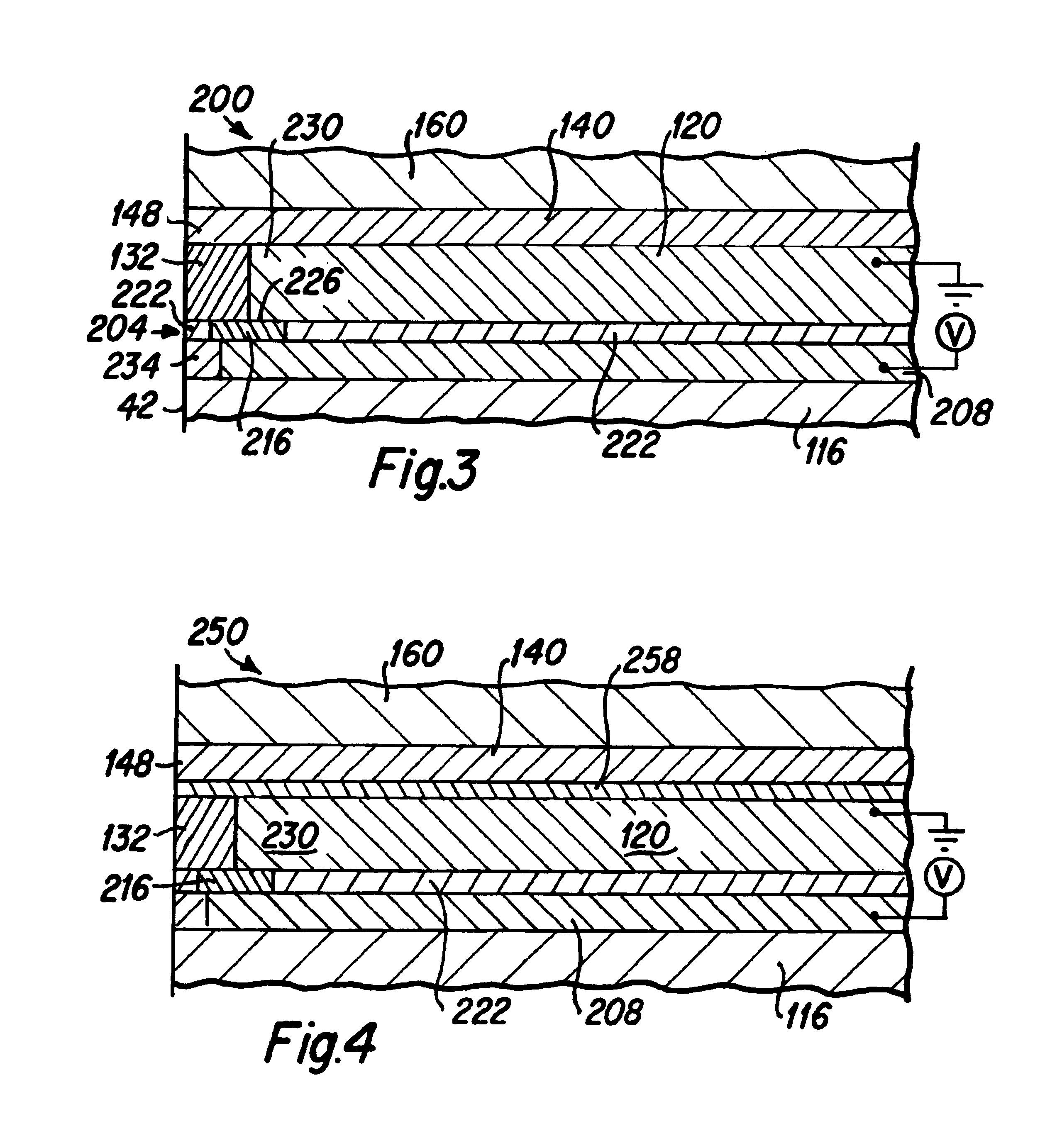
[0038]A further improvement that can be incorporated into the magnetic head embodiment 200 is that the insulation layer 132 which separates the front portion 230 of the shaping layer 120 from the ABS 42 can be composed of a more thermally conductive material, such as NiP, which then serves as a thermal conduction layer. The thermal conduction layer 132 serves to more efficiently radiate heat to the media which aids in the data bit writing process of the magnetic head. It is to be understood that the fabrication of the thermal conduction layer 132 in front of the shaping layer 120 can also be beneficially incorporated into the magnetic head embodiments that are subsequently described.

[0039]FIG. 4 is a side cross-sectional view depicting an alternative magnetic head embodiment 250 of the present invention having many similar features to the magnetic head embodiment 200 depicted in FIG. 3, and such features are identically numbered for ease of comprehension. To further avoid the possib...

embodiment 500

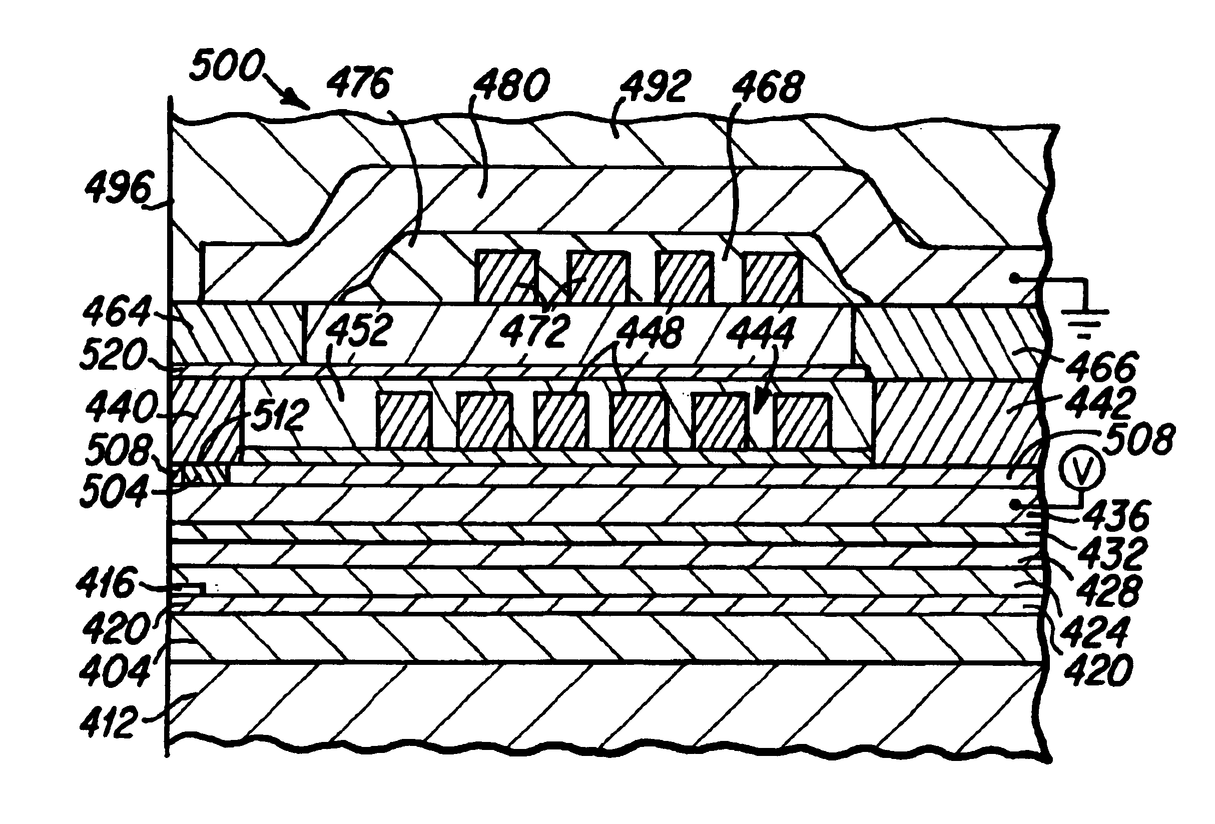
[0047]In this magnetic head embodiment 500, the write gap layer 520 is ideally fabricated from a material such as tantalum, rhodium, ruthenium or palladium that is electrically conductive while being nonconductive to magnetic flux passing therethrough. It is therefore to be understood that the electrical current path of the heating device passes from the P1 pole layer 436, through the heating element 504, through the P1 pole pedestal 440, through the write gap layer 520 and through P2 pole tip 464 and through the second magnetic pole yoke 480. Thus electrical current flows through the thickness of the heating element such that the current flow path is generally perpendicular to the planar thin film heating element 504. It is desirable that most of the voltage drop of the heating device be across the heating element 504. A desirable electrical potential across the heating element 504 is less than 2 volts where the heating element 504 has a resistivity of approximately 100 to 1,000 Ωc...


PUM

PropertyMeasurementUnit
thicknessaaaaaaaaaa
thicknessaaaaaaaaaa
widthaaaaaaaaaa

Abstract

An embodiment of a magnetic head of the present invention includes a media heating device that is fabricated within the magnetic head structure following the fabrication of the read head element of the magnetic head. The media heating device is preferably fabricated between the first and second magnetic pole layers and close to the ABS surface of the head. The heating device includes electrical leads and an electrically resistive heating element that is preferably comprised of TaSiN, NiCr or NiFe, and in the present invention one or both of the magnetic poles are utilized as an electrical lead of the heating device. The heating device serves to heat the magnetic media immediately prior to the passage of the magnetic media beneath the pole tip, which lowers the localized coercivity of the media and facilitates the writing of data to the media by the write head element of the magnetic head.

Description

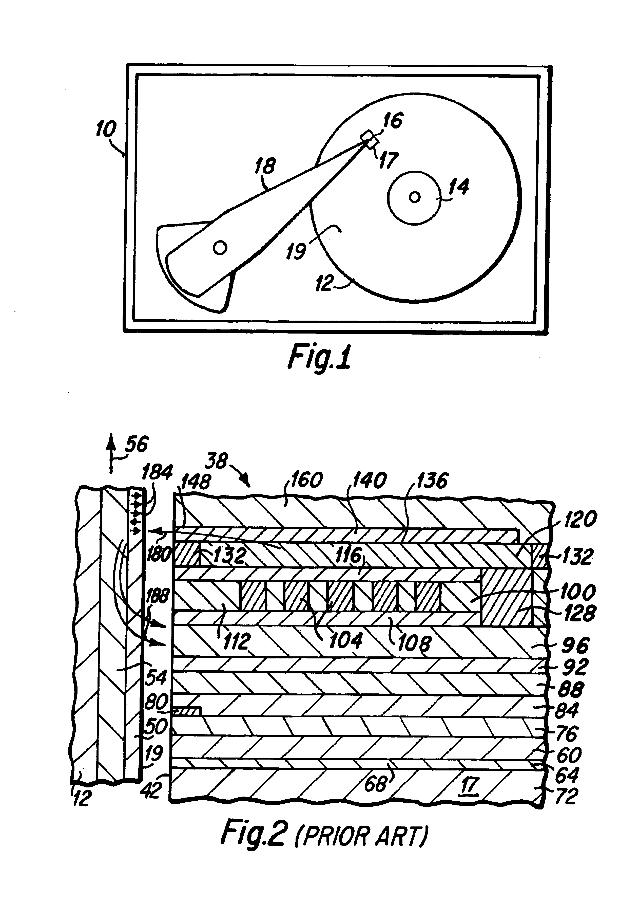
BACKGROUND OF THE INVENTION[0001]1. Field of the Invention[0002]The present invention relates generally to magnetic heads that are utilized with thin film hard disk data storage devices, and more particularly to the design and fabrication of a magnetic head having a storage media heating device formed therein, where a magnetic pole of the magnetic head serves as an electrical lead of the heating device.[0003]2. Description of the Prior Art[0004]Hard disk drives generally include one or more rotatable data storage disks having a magnetic data storage layer formed thereon. Data in the form of small magnetized areas, termed magnetic data bits, is written onto the magnetic layers of the disks by a magnetic head that includes magnetic poles through which magnetic flux is caused to flow. Magnetic flux flowing from a pole tip portion of the magnetic poles in close proximity to the magnetic layer on the disk, causes the formation of the magnetic bits within the magnetic layer.[0005]The cont...

Claims


Application Information

Patent Timeline
Patent Type & Authority Patents(United States)
IPC IPC(8): G11B5/31
CPCG11B5/3116
Inventor LILLE, JEFFREY S.SANTINI, HUGO ALBERTO EMILIO
Owner WESTERN DIGITAL TECH INC
Learn More