
Apparatus and method for low coherence ranging

a low-coherence range, optical coherence tomography technology, applied in the direction of instruments, scientific instruments, measurement devices, etc., can solve the problems of no known optical coherence tomography configuration, the use of optical coherence tomography (oct) is limited to the visualization of architectural morphological structures within biological tissues, and the imaging of sub-cellular features using oct is not well demonstrated

Inactive Publication Date: 2007-12-18
THE GENERAL HOSPITAL CORP
View PDF187 Cites 308 Cited by
  • Summary
  • Abstract
  • Description
  • Claims
  • Application Information

AI Technical Summary

Benefits of technology

The present invention relates to improving optical coherence tomography (OCT) by using an optical element to enhance transverse resolution and depth of focus. The invention aims to enable high transverse resolution and large depth of field cross-sectional OCT imaging, which is currently limited to visualizing architectural morphological structures within biological tissues. The invention proposes a simple device that can perform high transverse resolution, large depth of field OCT imaging over a large depth of focus. The technical effect of the invention is to enable OCT to perform sub-cellular level resolution imaging in applications requiring early diagnosis of epithelial cancers and other biomedical imaging diagnostics that require sub-cellular resolution imaging at remote sites within biological systems.

Problems solved by technology

Currently, the use of optical coherence tomography (OCT) is limited to the visualization of architectural morphological structures within biological tissues.
The imaging of sub-cellular features with OCT has not been well demonstrated because of the relatively poor transverse resolution required to preserve depth of focus.
To date, there are no known optical coherence tomography configurations that can perform high transverse resolution imaging over a large depth of field.

Method used


Image

  • Apparatus and method for low coherence ranging
  • Apparatus and method for low coherence ranging
  • Apparatus and method for low coherence ranging

Examples


Embodiment Construction

Definitions

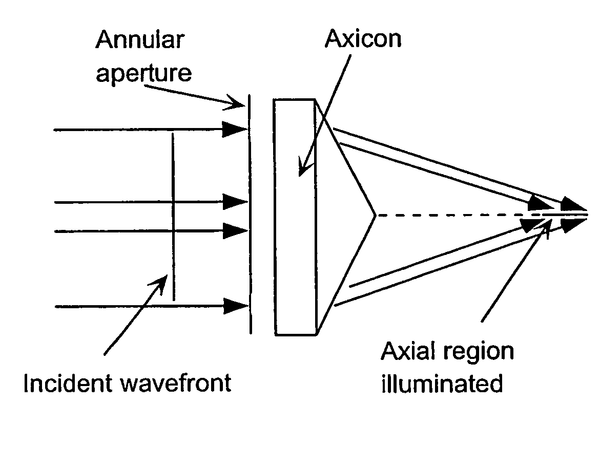
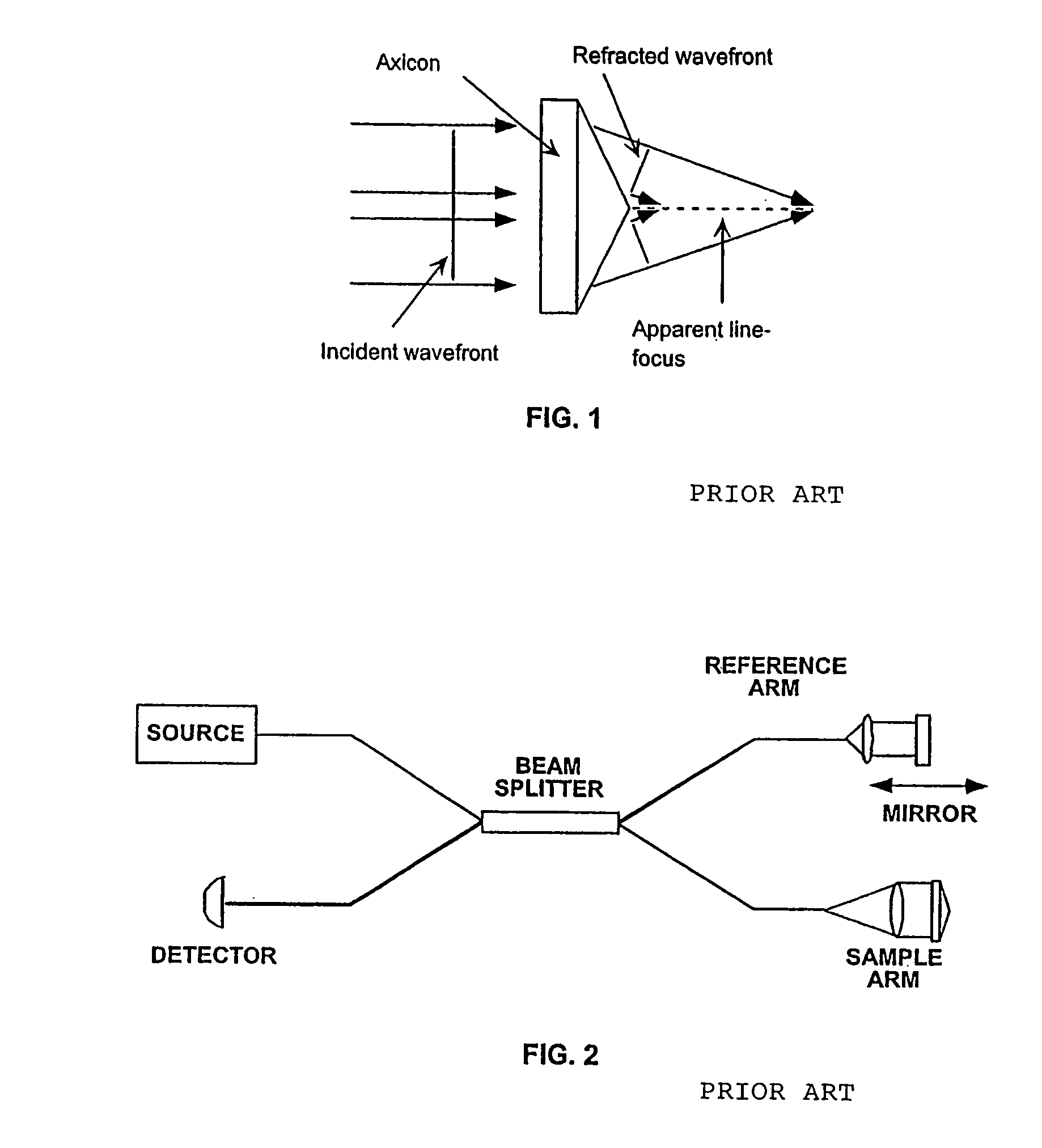
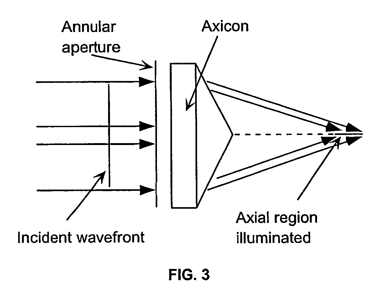
[0018]“Axicon” shall mean any optic element (or combination thereof) capable of generating an axial line focus. Refractive, diffractive, and reflective axicons have been demonstrated. See, J. H. McLeod, J. Opt. Soc. Am 44, 592 (1954); J. H. McLeod, J. Opt. Soc. Am 50, 166 (1960); and J. R. Rayces, J. Opt. Soc. Am. 48, 576 (1958).

[0019]“Depth of focus” shall mean the longitudinal distance over which the beam diameter increases by a factor ζ (typically ζ=sqrt(2) or 2). For a Gaussian beam, the sqrt(2) depth of focus is

[0020]2⁢zR=2⁢π⁡(d2)2λ.

[0021]For a typical Gaussian spot size (1 / e2 diameter) of d=5 μm, and a wavelength of 830 nm, the depth of focus is approximately 48 μm. The depth of focus for a uniform beam (3 dB full-width-half-maximum intensity response for a planar reflector moved through the longitudinal plane) may be defined as

[0022]zu≈.9⁢λNA2.

[0023]For a NA=0.2, which produces a spot size of 5 μm, the depth of focus for a uniform beam is approximately 17 μm at 830...


PUM

PropertyMeasurementUnit
distanceaaaaaaaaaa
depthaaaaaaaaaa
depthaaaaaaaaaa

Abstract

A system, apparatus and method for performing low coherence ranging of a sample with high transverse resolution and large depth of focus can be provided. For example, an optical ranging system including a light source can be used. Certain exemplary arrangement can be provided, e.g., a first arrangement for directing light from the light source to the sample, a second arrangement for directing reflected light from the sample to a detector, at least one detector, and a third arrangement for processing light data received by the detector and which generates an image can be utilized. Further, for example, an optical element can be provided which can have a transverse resolution defined as .Δris less than or equal to about μ5 m, and a depth of focus Δz of at least about 50 μm.

Description

CROSS-REFERENCE TO RELATED APPLICATION[0001]This application claims the priority benefit of co-pending U.S. Provisional Application No. 60 / 347,528 filed Jan. 11, 2002, which is hereby incorporated by reference in its entirety.FIELD OF THE INVENTION[0002]The present invention relates to apparatus for imaging tissue samples using optical coherence tomography and incorporating an optical element to improve transverse resolution and depth of focus.BACKGROUND OF THE INVENTION[0003]Currently, the use of optical coherence tomography (OCT) is limited to the visualization of architectural morphological structures within biological tissues. The imaging of sub-cellular features with OCT has not been well demonstrated because of the relatively poor transverse resolution required to preserve depth of focus. The capability to perform high transverse resolution, large depth of field cross-sectional OCT imaging would permit application to early diagnosis of epithelial cancers and other biomedical i...

Claims


Application Information

Patent Timeline
Patent Type & Authority Patents(United States)
IPC IPC(8): G01B9/02G01N21/47G01N21/17
CPCG01N21/4795G01B9/02028G01B9/02036G01B9/02091G01B9/02035
Inventor GUILLERMO, TEARNEY J.BOUMA, BRETT E.
Owner THE GENERAL HOSPITAL CORP
Learn More